The mighty power lines that criss-cross
our countryside or wiggle unseen beneath city streets carry electricity
at enormously high voltages from power
plants to our homes. It's not unusual for a power line to be rated
at 300,000 to 750,000 volts—and some lines operate at even higher voltages.
[1]
But the appliances in our homes use voltages thousands of times smaller—typically just 110 to 250 volts. If
you tried to power a toaster or a TV set from an electricity pylon, it would
instantly explode! (Don't even think about trying, because the
electricity in overhead lines will almost certainly kill you.) So there has to
be some way of reducing the high voltage electricity from power plants to
the lower voltage electricity used by factories, offices, and homes.
The piece of equipment that does this, humming with electromagnetic
energy as it goes, is called a transformer.
Let's take a closer look at how it works!
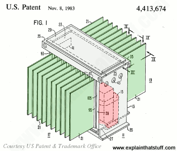
Photo: A typical small electricity transformer supplying houses from the main power grid. Note the cooling fins (those vertical metal plates) on the four sides.
Your first question is probably this: if our homes and offices are
using photocopiers,
computers,
washing machines, and electric shavers
rated at 110–250 volts, why don't power stations simply transmit
electricity at that voltage? Why do they use such high voltages? To
explain that, we need to know a little about how electricity travels.
As electricity flows down a metal
wire, the electrons that carry its energy
jiggle through the metal structure, bashing and crashing about and
generally wasting energy like unruly
schoolchildren running down a corridor. That's why wires get hot when
electricity flows through them (something that's very useful in electric toasters and other
appliances that use heating elements). It turns out that
the higher the voltage electricity you use, and the lower the current,
the less energy is wasted in this way. So the electricity that comes
from power plants is sent down the wires at extremely high voltages to
save energy.
Photo: Coming down: This old substation (step-down electricity transformer) supplies power in the small English village where I live. It's about 1.5m (5ft) high and its job is to convert several thousand volts of incoming electricity to the hundreds of volts we use in our homes.
But there's another reason too. Industrial plants have huge factory
machines that are much bigger and more energy-hungry than anything you
have at home. The energy an appliance uses is directly related (proportional)
to the voltage it uses. So, instead of running on 110–250 volts, power-hungry machines might use
10,000–30,000 volts. Smaller factories and machine shops may need
supplies of 400 volts or so. In other words, different electricity
users need different voltages. It makes sense to ship high-voltage
electricity from the power station and then transform it to
lower voltages when it reaches its various destinations. (Even so, centralized power stations
are still very inefficient. About two thirds of the energy that arrives at a power plant,
in the form of raw fuel, is wasted in the plant itself and on the journey to your home.)
Photo: Making large electricity transformers at a Westinghouse factory during World War II.
Photo by Alfred T. Palmer, Office of War Administration, courtesy of US Library of Congress.
Sponsored links
How does a transformer work?
A transformer is based on a very simple fact about electricity: when
a fluctuating electric current flows through a wire, it generates a magnetic
field (an invisible pattern of magnetism) or "magnetic flux" all
around it. The strength of the magnetism (which has the rather
technical name of magnetic flux density) is
directly related to
the size of the electric current. So the bigger the current, the
stronger the magnetic field. Now there's another interesting fact about
electricity too. When a magnetic field fluctuates around a piece of
wire, it generates an electric current in the wire. So if we put a
second coil of wire next to the first one, and send a fluctuating
electric current into the first coil, we will create an electric
current in the second wire.
The current in the first coil is usually
called the primary current and the current
in the second wire
is (surprise, surprise) the secondary current.
What we've done
here is pass an electric current through empty space from one coil of
wire to another. This is called electromagnetic
induction because the current in the first coil
causes (or "induces") a current in the second coil.
We can make electrical energy pass more efficiently from one coil to
the other by wrapping them around a soft iron bar (sometimes called a core):
To make a coil of wire, we simply curl the wire round into loops or
("turns" as physicists like to call them). If
the second coil
has the same number of turns as the first coil, the electric current in
the second coil will be virtually the same size as the one in the first
coil. But (and here's the clever part) if we have more or fewer turns
in the second coil, we can make the secondary current and voltage
bigger or smaller than the primary current and voltage.
One important thing to note is that this trick works only if the
electric current is fluctuating in some way. In other words, you have
to use a type of constantly reversing electricity called alternating
current (AC) with a transformer. Transformers do not work with direct current (DC), where a steady current constantly flows in the same
direction.
Step-down transformers
If the first coil has more turns that the second coil, the secondary
voltage is smaller than the
primary voltage:
This is called a step-down
transformer. If the second coil has half
as many turns as the first coil, the secondary voltage will be half the
size of the primary voltage; if the second coil has one tenth as many
turns, it has one tenth the voltage. In general:
Secondary voltage ÷
Primary voltage = Number of turns in secondary ÷ Number of turns
in primary
The current is transformed the opposite way—increased in size—in a
step-down transformer:
Secondary current ÷ Primary current = Number of turns in
primary ÷ Number of turns in secondary
So a step-down transformer with 100 coils in the primary and 10
coils in the secondary will reduce the voltage by a factor of 10 but
multiply the current by a factor of 10 at the same time. The power in
an electric current is equal to the current times the voltage (watts =
volts x amps is one way to remember this), so you can see the power in
the secondary coil is theoretically the same as the power in the
primary coil. (In reality, there is some loss of power between the
primary and the secondary because some of the "magnetic flux" leaks out
of the core, some energy is lost because the core heats up, and so on.)
Step-up transformers
Reversing the situation, we can make a step-up
transformer that boosts a
low voltage into a high one:
This time, we have more turns on the secondary
coil than the primary. It's still true that:
Secondary voltage ÷ Primary voltage = Number of turns in
secondary ÷ Number of turns in primary
and
Secondary current ÷ Primary current = Number of turns in
primary ÷ Number of turns in secondary
In a step-up transformer, we use more turns in the secondary than in
the primary to get a bigger secondary voltage and a smaller secondary
current.
Considering both step-down and step-up transformers, you can see it's a general rule that
the coil with the most turns has the highest voltage, while the coil with the fewest turns
has the highest current.
Transformers in your home
Photo: Typical home transformers. Anticlockwise
from top left: A modem transformer, the white transformer in an iPod
charger, and a cellphone charger.
As we've already seen, there are lots of huge transformers in towns
and cities where the high-voltage electricity from incoming power lines
is converted into lower-voltages. But there are lots of transformers in
your home also. Big electric appliances such as washing machines and dishwashers use relatively high voltages
of 110–240 volts, but electronic devices such as laptop computers and chargers for MP3 players and mobile cellphones use relatively tiny
voltages: a laptop needs about 15 volts, an iPod charger needs 12
volts, and a cellphone typically needs less than 6 volts when you
charge up its battery. So electronic appliances like these have small
transformers built into them (often mounted at the end of the power
lead) to convert the 110–240 volt domestic
supply into a smaller voltage they can use. If you've ever wondered why
things like cellphones have those big fat chunky power cords, it's because
they contain transformers!
Photos: An electric toothbrush standing on its charger. The battery in the brush charges by induction: there is no direct electrical contact between the plastic brush and the plastic charger unit in the base. An induction charger is a special kind of transformer split into two pieces, one in the base and one in the brush. An invisible magnetic field links the two parts of the transformer together.
Induction chargers
Many home transformers (like the ones used by iPods and
cellphones) are designed to charge up rechargeable batteries.
You can see exactly how they work: electricity flows
into the transformer from the electricity outlet on your wall, gets
transformed down to a lower voltage, and flows into the battery in your
iPod or phone. But what happens with something like an electric toothbrush, which has no
power lead? It charges up with a slightly different type of
transformer, which has one of its coils in the base of the brush and
the other in the charger that the brush stands on. You can find out
how transformers like this work in our article about induction chargers.
Transformers in practice
Photo: Blast from the past: A strangely shaped transformer at the Chickamauga Dam near Chattanooga, Tenn.
Photographed in 1942 by Alfred T. Palmer, Office of War Administration, courtesy of US Library of Congress.
If you've got some of these transformer chargers at home (normal ones or induction chargers), you'll have noticed that they get warm after they've been on for a while. Because all transformers produce some waste heat, none of them are perfectly efficient: less electrical energy is produced by the secondary coil than we feed into the primary, and the waste heat accounts for most of the difference.
On a small home cellphone charger, the heat loss is fairly minimal (less than that from an old-fashioned, incandescent light bulb) and not usually something to worry about.
But the bigger the transformer, the bigger the current it carries and the more heat it produces. For a substation transformer like the one in our photo up above, which is about as wide as a small car, the waste heat can be really significant: it can damage the transformer's insulation, seriously shorten its life, and make it much less reliable (let's not forget that hundreds or even thousands of people can depend on the power from a single transformer, which needs to operate reliably not just from day to day, but from year to year).
That's why the likely temperature rise of a transformer during operation is a very important factor in its design. The typical "load" (how heavily it's used), the seasonal range of outdoor (ambient) temperatures, and even the altitude (which reduces the density of the air and therefore how effectively it cools something) all need to be taken into account to figure out how effectively an outdoor transformer will operate.
In practice, most large transformers have built-in cooling systems that use air, liquid (oil or water), or both to remove any waste heat. Typically, the main part of the transformer (the core, and the primary and secondary windings) is immersed in an oil tank with a heat exchanger,
pump, and cooling fins attached. Hot oil is pumped from the top of the transformer through the heat exchanger (which cools it down) and back into the bottom, ready to repeat the cycle. Sometimes the oil moves around a cooling circuit by convection alone without the use of a separate pump. Some transformers have electric fans that blow air past the heat exchanger's cooling fins to dissipate heat more effectively.
Artwork: Large transformers have built-in cooling systems. In this case, the transformer core and coil (red) sit inside a large oil tank (gray). Hot oil taken from the top of the tank circulates through one or more heat exchangers, which dissipate the waste heat using cooling fins (green), before returning the oil to the same tank at the bottom. Artwork from US Patent 4,413,674: Transformer Cooling Structure by Randall N. Avery et al, Westinghouse Electric Corp., courtesy of US Patent and Trademark Office.
What are solid-state transformers?
You will have gathered from reading what's above that transformers can be very big, very clumsy, and sometimes very inefficient.
Since the mid-20th century, all kinds of neat electric tricks that used to be carried out by large (and sometimes mechanical)
components have been done electronically instead, using what's called "solid-state" technology.
So, for example, switching and amplifying relays have been swapped
for transistors,
while magnetic hard drives have increasingly been replaced by flash memory
(in such things as solid-state drives, SSDs, and USB memory sticks).
Over the last few decades, electronic engineers have been working to develop what are called solid-state transformers (SST).
These are essentially compact, high-power, high-frequency semiconductor circuits that increase or decrease voltages with better reliability and
efficiency than traditional transformers; they're also much more controllable, so more
responsive to changes in supply and demand. "Smart grids" (future power-transmission systems, fed by intermittent sources of
renewable energy, such as wind turbines and solar farms),
are therefore going to be a major application. Despite huge interest, SST
technology remains relatively little used so far, but it's likely to be
the most exciting area of transformer design in the future.
Transformer and Inductor Design Handbook by Colonel William T. McLyman. CRC Press, 2011. A detailed, practical guide to designing electrical machines using inductance.
Electrical Transformers and Power Equipment by Anthony J. Pansini. Fairmont Press, 1999. Explains the theory, construction, installation, and maintenance of transformers and the different types of transformers before going on to cover related power devices such as circuit breakers, fuses, and protective relays.
Transformers and Motors by George Patrick Schultz. Newnes, 1997. This book has a much more "hands-on," practical feel than some of the other books listed here; it's intended more for electricians and people who have to work with transformers than those who want to design them.
More general books for younger readers
DK Eyewitness: Electricity by Steve Parker. Dorling Kindersley, 2005. A historic look at electricity and how people have put it to practical use.
Power and Energy by Chris Woodford. Facts on File, 2004. One of my own books, this describes how humans have harnessed energy (including electricity) throughout history.
Patents
There are hundreds of patents covering electricity transformers of different kinds. Here are a few particularly interesting (early) ones from the US Patent and Trademark Office database:
US Patent 351,589: System of electric distribution by Lucien Gaulard and John Gibbs, October 26, 1886. Gaulard and Gibbs outline how transformers can be used to step up and step down voltages for efficient power distribution—the basis of the modern electricity supply system throughout the world.
US Patent 497,113: Transformer motor by Otto Titus Bláthy, May 9, 1893. A combined transformer and motor produced by one of the inventors of the transformer.
The Transformers: Superheroes of Electrical Inventions by Vaclav Smil. IEEE Spectrum. July 25, 2017. There are billions of transformers on the planet—in your smartphone, your laptop, your toothbrush, and elsewhere; isn't it time we appreciated them a bit more? Includes a potted history.
Next for the Grid: Solid State Transformers by Michael Kanellos, Green Tech Media, March 15, 2011. An overview of how solid-state transformers could revolutonize our power grids.
↑ Transmission voltages vary from country to country according to the distance over which electricity needs to be sent, but typically range from about 45,000–750,000 volts
(45–750 kV). However, some long-distance lines operate at voltages of over 1 million volts (1,000,000 volts or 1000 kv).
See Protection Technologies of Ultra-High-Voltage AC Transmission Systems by Bin Li et al. Elsevier, 2020, pp.1–5.
High-voltage lines are classed as 45–300 kV; extra-high voltage range from 300 kV–750 kV; and ultra-high voltages are generally above 800 kV, according to Overhead Power Lines: Planning, Design, Construction by Friedrich Kiessling et al,
Springer, 2003/2014, p.6.
Please do NOT copy our articles onto blogs and other websites
Articles from this website are registered at the US Copyright Office. Copying or otherwise using registered works without permission, removing this or other copyright notices, and/or infringing related rights could make you liable to severe civil or criminal penalties.