Your brain contains around 100 billion cells called neurons—the tiny switches that let you think and remember things.
Computers contain billions
of miniature "brain cells" as well. They're called transistors and
they're made from silicon, a chemical element commonly found in sand.
Transistors have revolutionized electronics since they were first
invented over half a century ago by John Bardeen, Walter Brattain, and
William Shockley. But what are they—and how do they work?
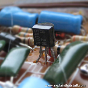
Photo: An insect with three legs? No, a typical transistor on an electronic circuit board. Although simple circuits contain individual transistors like this, complex circuits inside computers also contain microchips, each of which might have thousands, millions, or hundreds of millions of transistors packed inside. (Technically, if you're interested in the more geeky bits, this is a 5401B silicon PNP amplifier transistor. I'll explain what all that stuff means in a moment.)
A transistor is really simple—and really complex. Let's start with
the simple part. A transistor is a miniature electronic component that
can do two different jobs. It can work either as an amplifier or a switch:
When it works as an amplifier, it takes
in a tiny electric current at one end (an
input current) and produces a much bigger electric current (an output
current) at the other. In other words, it's a kind of current booster. That comes in
really useful in things like hearing aids, one of the first things
people used transistors for. A hearing aid has a tiny microphone in it
that picks up sounds from the world around you and turns them into
fluctuating electric currents. These are fed into a transistor that
boosts them and powers a tiny loudspeaker,
so you hear a much louder version of the sounds around you.
William Shockley, one of the inventors of the transistor, once explained transistor-amplifiers to a student in a more
humorous way: "If you take a bale of hay and tie it to the
tail of a mule and then strike a match and set the bale of hay on fire,
and if you then compare the energy expended shortly thereafter by the
mule with the energy expended by yourself in the striking of the match,
you will understand the concept of amplification."
Transistors can also work as switches. A
tiny electric current flowing through one part of a transistor can make a much bigger
current flow through another part of it. In other words, the small
current switches on the larger one. This is essentially how all computer chips work. For
example, a memory chip
contains hundreds of millions or even billions of transistors,
each of which can be switched on or off individually. Since each
transistor can be in two distinct states, it can
store two different numbers, zero and one. With billions of transistors, a chip can store billions of zeros and ones, and
almost as many ordinary numbers and letters (or characters, as we call them). More about this in a moment.
Photo: Compact hearing aids were among the first applications for transistors—and this one dates from about the late 1950s or 1960s. About the size of a pack of playing cards, it was designed to be worn in or on a jacket pocket. There's a microphone on the other side of the case that picks up ambient sounds. You can clearly see the four little black transistors inside, amplifying those sounds and then shooting them out to the little loudspeaker (bottom) that sits in your ear.
The great thing about old-style machines was that you could take
them apart to figure out how they worked. It was never too hard, with a
bit of pushing and poking, to discover which bit did what and how one
thing led to another. But electronics is entirely different. It's all
about using electrons to control electricity. An electron is a
minute
particle inside an atom. It's so small, it weighs just under
0.000000000000000000000000000001 kg! The most advanced transistors work
by controlling the movements of individual electrons, so you can
imagine just how small they are. In a modern computer chip, the size of
a fingernail, you'll probably find between 500 million
and two billion separate transistors. There's no chance of taking a transistor apart to find out how it
works, so we have to understand it with theory and imagination instead.
First off, it helps if we know what a transistor is made from.
Sponsored links
How is a transistor made?
Transistors are made from silicon, a chemical element found in sand, which does not normally conduct
electricity (it doesn't allow electrons to flow through it easily).
Silicon is a semiconductor, which means it's
neither really a
conductor (something like a metal that lets electricity flow) nor an
insulator (something like plastic that stops electricity flowing). If
we treat silicon with impurities (a process known as doping),
we can make it behave in a different
way. If we dope silicon with the chemical elements arsenic, phosphorus,
or antimony, the silicon gains some extra "free" electrons—ones that
can carry an electric current—so electrons will flow out
of it more naturally. Because electrons have a negative charge, silicon
treated this way is called n-type (negative
type). We can also dope silicon with other impurities such as boron,
gallium, and aluminum. Silicon treated this way has fewer of those
"free" electrons, so the electrons in nearby materials will tend to flow into it. We call this sort of silicon p-type (positive type).
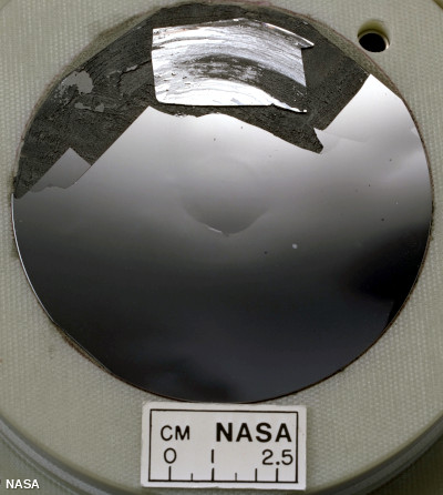
Photo: A wafer of silicon. Photo by courtesy of NASA Glenn Research Center (NASA-GRC)and
Internet Archive.
Quickly, in passing, it's important to note that neither n-type or p-type silicon actually has a charge in itself: both are electrically neutral. It's true that n-type silicon has extra "free" electrons that increase its conductivity, while p-type silicon has fewer of those free electrons, which helps to increase its conductivity in the opposite way. In each case, the extra conductivity comes from having added neutral (uncharged) atoms of impurities to silicon that was neutral to start with—and we can't create electrical charges out of thin air! A more detailed explanation would need me to introduce an idea called
band theory, which is a little bit beyond the scope of this article. All we need to remember is that "extra electrons" means extra free electrons—ones that can freely move about and help to carry an electric current.
Silicon sandwiches
We now have two different types of silicon. If we put them together
in layers, making sandwiches of p-type and n-type material, we can make
different kinds of electronic components that work in all kinds of
ways.
Artwork: Join n-type silicon to p-type silicon and you get an n-p junction, which is the basis of diodes and transistors.
Suppose we join a piece of n-type silicon to a piece of p-type
silicon and put electrical contacts on either side. Exciting and useful
things start to happen at the junction between the two
materials. If we turn
on the current, we can make electrons flow through the junction from
the n-type side to the p-type side and out through the circuit. This
happens because the lack of electrons on the p-type side of the
junction pulls electrons over from the n-type side and vice-versa. But
if
we reverse the current, the electrons won't flow at all. What we've
made here is called a diode (or rectifier).
It's an electronic
component that lets current flow through it in only one direction. It's
useful if you want to turn alternating (two-way) electric current into
direct (one-way) current. Diodes can also be made so they give off
light when electricity flows through them. You might have seen these
light-emitting diodes (LEDs) on pocket calculators and electronic
displays on hi-fi stereo equipment.
How a junction transistor works
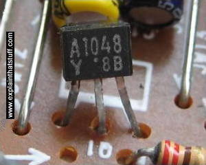
Photo: A typical silicon PNP transistor (an A1048 designed as an audio-frequency amplifier).
Now suppose we use three layers of silicon in our sandwich instead
of two. We can either make a p-n-p sandwich (with a slice of n-type
silicon as the filling between two slices of p-type) or an n-p-n
sandwich (with the p-type in between the two slabs of n-type). If we
join electrical contacts to all three layers of the sandwich, we can
make a component that will either amplify a current or switch it on or
off—in other words, a transistor. Let's see how it works in the case of an
n-p-n transistor.
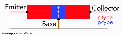
So we know what we're talking about, let's give names to the three
electrical contacts. We'll call the two contacts joined to the two
pieces of n-type silicon the emitter and the collector,
and the contact
joined to the p-type silicon we'll call the base. When no
current is
flowing in the transistor, we know the p-type silicon is short of
electrons (shown here by the little plus signs, representing positive
charges) and the two pieces of n-type silicon have extra electrons
(shown by the little minus signs, representing negative charges).
Another way of looking at this is to say that while the n-type has a
surplus of electrons, the p-type has holes where electrons
should be. Normally, the holes in the base act like a barrier, preventing any
significant current flow from the emitter to the collector while
the transistor is in its "off" state.
A transistor works when the electrons and the holes start moving
across the two junctions between the n-type and p-type silicon.
Let's
connect the transistor up to some power. Suppose we attach a small
positive voltage to the base, make the emitter negatively charged, and
make the collector positively charged. Electrons are pulled from the
emitter into the base—and then from the base into the collector. And
the transistor switches to its "on" state:
The small current that we turn on at the base makes a big current
flow between the emitter and the collector. By turning a small input
current into a large output current, the transistor acts like an amplifier. But
it also acts like a switch at the same time. When there is no current to
the base, little or no current flows between the collector and the
emitter. Turn on the base current and a big current flows. So the base
current switches the whole transistor on and off. Technically, this
type of transistor is called bipolar because
two different kinds (or "polarities") of electrical charge (negative electrons and
positive holes) are involved in making the current flow.
We can also understand a transistor by thinking of it like a pair of diodes. With the
base positive and the emitter negative, the base-emitter junction is like a forward-biased
diode, with electrons moving in one direction across the junction (from left to right in
the diagram) and holes going the opposite way (from right to left). The base-collector
junction is like a reverse-biased diode. The positive voltage of the collector pulls
most of the electrons through and into the outside circuit (though some electrons do recombine with holes in the base).
How a field-effect transistor (FET) works
All transistors work by controlling the movement of electrons, but
not all of them do it the same way. Like a junction transistor, a FET
(field effect transistor) has three different terminals—but they
have the names source (analogous to the emitter), drain
(analogous to the
collector), and gate (analogous to the base). In a FET, the
layers of
n-type and p-type silicon are arranged in a slightly different way and
coated with layers of metal and oxide. That gives us a device called a
MOSFET (Metal Oxide Semiconductor Field
Effect Transistor).
Although there are extra electrons in the n-type source and drain,
they cannot flow from one to the other because of the holes in
the p-type gate in between them. However, if we attach a positive
voltage to the gate, an electric field is created there that allows
electrons to flow in a thin channel from the source to the drain. This
"field effect" allows a current to flow and switches the transistor on:
For the sake of completeness, we could note that a MOSFET is a unipolar
transistor because only one kind ("polarity")
of electric charge is involved in making it work.
How do transistors work in calculators and computers?
In practice, you don't need to know any of this stuff about
electrons and holes unless you're going
to design computer chips for a living! All you need to know is that a
transistor works like an amplifier or a switch, using a small current
to switch on a larger one. But there's one other thing worth knowing:
how does all this help computers store
information and make decisions?
We can put a few transistor switches together to make something
called a logic gate, which compares several
input currents and gives a different output as a result. Logic gates let computers make
very simple decisions using a mathematical technique called Boolean algebra. Your brain makes decisions the same way. For example,
using "inputs" (things you know) about the weather and what you have in
your hallway, you can make a decision like this: "If it's raining AND I
have an umbrella, I will go to the
shops". That's an example of Boolean algebra using what's called an AND
"operator" (the word operator is just a bit of mathematical jargon to
make things seem more complicated than they really are). You can make
similar decisions with other operators. "If it's windy OR it's snowing,
then I will put on a coat" is
an example of using an OR operator. Or how about "If it's raining AND I
have an umbrella OR I have a coat then it's okay to go out". Using AND,
OR, and other operators called
NOR, XOR, NOT, and NAND, computers can add up or compare binary numbers.
That idea is the foundation stone of computer programs: the logical
series of instructions that make computers do things.
Normally, a junction transistor is "off" when there is no base
current and switches to "on" when the base current flows. That means it
takes an electric current to switch the transistor on or off. But
transistors like this can be hooked up with logic gates so their output
connections feed back into their inputs. The transistor
then stays on even when the base current is removed. Each time a new
base
current flows, the transistor "flips" on or off. It remains in one of
those stable states (either on or off) until another current
comes along and flips it the other way. This kind of arrangement
is known as a flip-flop and it turns a
transistor into a simple
memory device that stores a zero (when it's off) or a one (when it's
on). Flip-flops are the basic technology behind computer memory chips.
Who invented the transistor?
Artwork: The original design of the point-contact transistor, as set out in
John Bardeen and Walter Brattain's US patent (2,524,035), filed in June 1948 (about six months after
the original discovery) and awarded October 3, 1950. This is a simple PN transistor with a
thin upper layer of P-type germanium (yellow) on a lower layer of N-type germanium (orange).
The three contacts are emitter (E, red), collector (C, blue), and base (G, green).
You can read more in the original patent document, which is listed in the references below.
Artwork courtesy of US Patent and Trademark Office.
Transistors were invented at Bell Laboratories in New Jersey in 1947
by three brilliant US physicists: John Bardeen (1908–1991), Walter
Brattain (1902–1987), and William
Shockley (1910–1989).
The team, led by Shockley, had been trying to
develop a new kind of amplifier for the US telephone system—but what
they actually invented turned out to have much more widespread
applications. Bardeen and Brattain made the first practical transistor
(known as a point-contact transistor) on Tuesday, December 16, 1947.
Although Shockley had played a large part in the project, he was
furious and agitated at being left out. Shortly afterward, during a
stay in a hotel at a physics conference, he single-handedly figured out
the theory of the junction transistor—a much better device than the
point-contact transistor.
While Bardeen quit Bell Labs to become an academic (he went on to
enjoy even more success studying superconductors at the University of Illinois),
Brattain stayed for a while before retiring to become a teacher.
Shockley set up his own transistor-making company and helped to inspire
the modern-day phenomenon that is "Silicon Valley" (the prosperous area
around Palo Alto, California where electronics corporations have
congregated). Two of his employees, Robert Noyce and Gordon Moore, went
on to found Intel, the world's biggest micro-chip manufacturer.
Bardeen, Brattain, and Shockley were briefly reunited a few years later when
they shared the world's top science
award, the
1956 Nobel Prize in Physics,
for their discovery. Their story is
a riveting tale of
intellectual brilliance battling with petty jealousy and it's well
worth reading
more about. You can find some great accounts of it among the books and
websites listed below.
Transistorized!: A PBS website about Bardeen, Brattain, Shockley, and the history of the transistor.
The Transistor: Learn about transistors in a fun way, with games and interactives on the Nobel Prize website.
[Archived via the Wayback Machine.]
Books
Technical and practical
Make: Electronics by Charles Platt. O'Reilly, 2015. A clear, well-illustrated primer for electronics beginners and a great place for a keen teenager to start. Experiment 10 begins the coverage of transistors.
Getting Started in Electronics by Forrest M. Mims III. Master Publishing, 2003. Dependable introduction with lots of example circuits to try.
The Art of Electronics by Paul Horowitz, Winfield Hill. Cambridge University Press, 2015. This is a much more detailed undergraduate textbook—and the one I used myself at college.
Why Things Are the Way They Are by B.S. Chandrasekhar. Cambridge University Press, 1998. A relatively easy-to-follow, mostly non-mathematical introduction to solid-state physics; in effect, it explains how solids really work from the inside. Chapter 10 explains electric currents and semiconductors.
Hail the Perovskite Transistors by David Schneider. IEEE Spectrum, 16 January 2019. How perovskite crystals can be "painted" onto a substrate to make field-effect transistors.
Intel goes 3D with transistor redesign by Charles Arthur, Guardian, 4 May 2011. Making "three-dimensional" transistors allows engineers to cram even more of them into the same space.
MAKE presents: The Transistor: An excellent, easy-to-follow, 9-minute intro to transistors from Collin Cunningham of MAKE. Explains the difference between low-power (signal) transistors and high-powered devices, why transistors were better than vacuum tubes, and what we can use transistors for. There's also a very good explanation of the original Bardeen and Brattain point-contact transistors.
Historical
We're fortunate to have some surviving archive footage of the three transistor pioneers!
AT&T Archives: Bottle of Magic: How electron tubes made possible amplification of long-distance telephone calls. Transistors were the next logical step and were originally developed for exactly the same purpose.
Please do NOT copy our articles onto blogs and other websites
Articles from this website are registered at the US Copyright Office. Copying or otherwise using registered works without permission, removing this or other copyright notices, and/or infringing related rights could make you liable to severe civil or criminal penalties.