William Shockley, Nobel-Prize winning co-inventor of the transistor (a revolutionary
electronic amplifier dating from the 1940s) had a vivid way of
explaining it: "If you take a bale of hay and tie it to the tail of
a mule and then strike a match and set the bale of hay on fire, and
if you then compare the energy expended shortly thereafter by the
mule with the energy expended by yourself in the striking of the
match, you will understand the concept of amplification."
Amplifiers are the tiny components in hearing aids that make voices
sound louder. They're also the gadgets in radios that boost
faraway signals and the devices in stereo equipment that drive your
loudspeakers and the huge black boxes you plug into
electric guitars to make them raise the roof. What are amplifiers? How do they work?
Let's take a closer look!
An amplifier (often loosely called an "amp") is an electromagnetic or
electronic component that boosts an electric current. If you
wear a hearing aid, you'll know it uses a
microphone to pick up
sounds from the world around you and convert them into a fluctuating
electric current (a signal) that constantly changes in
strength. A transistor-based amplifier takes the signal (the input)
and boosts it many times before feeding it into a tiny loudspeaker
placed inside your ear canal so you hear a much-magnified version of
the original sounds (the output).
It's easy to calculate how much difference an amplifier makes: it's the ratio of the output
signal to the input signal, a measurement called the gain of an amplifier
(or sometimes the gain factor or amplification factor). So an
amplifier that doubles the size of the original signal has a gain of
2. For audio (sound) amplifiers, the gain is often expressed in
decibels (specifically, it's ten times the logarithm of the output power divided by the input power).
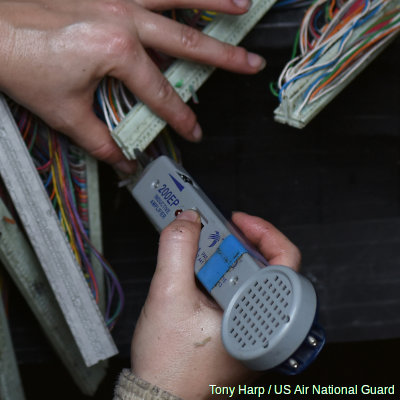
Photo: Testing telephone circuits with an inductive amplifier. It's a type of probe that can test a circuit without direct electrical contact and works through electromagnetic induction, a bit like
induction chargers. Photo by Tony Harp courtesy of US Air National Guard and DVIDS.
Sponsored links
Distortion and feedback
Now the key thing about an amplifier is not just that it boosts an electric current.
That's the easy bit. The hard bit is that it must faithfully reproduce the quality of the
input signal even when that signal is constantly (and sometimes dramatically) varying
in both frequency and amplitude (for an audio amplifier, that means
volume).
An audio amplifier might work better with some sound frequencies than others; the range
of frequencies over which it works satisfactorily is called its
bandwidth. Ideally, it has to produce a reasonably flatresponse or linear response with a wide range of
different input signals (so the gain is pretty much constant across a
range of frequencies). If the amplifier doesn't faithfully reproduce
input frequencies in its output, it suffers from what's called a
frequency response, which means it boosts some
frequencies more than others. (Sometimes this effect is deliberate.
Small earbud headphones are often designed this way so
they give extra bass.)
Charts: Top: Linear amplification: If the gain of an amplifier is always the same, no matter what the input signal, we call that a linear response. Here you can see that the output (vertical axis) is always ten times greater than the input (horizontal axis). Bottom: Clipping: In practice, no amplifier will have a perfectly linear response: it can only amplify so much. If the input signal is too large, the response will be linear up to a point and then "clipped" beyond it: even if you increase the input, the output doesn't increase as much.
Amplifiers also have to work across a wide range of amplitudes (typically that means sound volumes),
which leads to another problem. As the input amplitude increases, the amplifier will struggle to produce a
corresponding increase in output, because there's a limit to how much
power it can make. That means any further increases in the input
will simply produce the same level of output—a phenomenon known as
clipping—and increasing amounts of distortion.
Another problem amplifiers have is called feedback—and people who use
microphones on stage are very familiar with it. If a microphone is
turned up too much or placed too near to a loudspeaker, it picks up
not only the sound of a person's voice or an instrument (as it's
supposed to), but also the amplified sound of the voice or instrument
coming from the speaker slightly after, which is then
re-amplified—only to pass through the speaker once more and be
amplified yet again. The result is the horribly deafening whistle we
call feedback. Many rock stars and groups have made feedback effects
a deliberate part of their sound, including Jimi Hendrix and Nirvana.
Artwork: How feedback occurs: Top: When the microphone (left) picks up sound (red arrow), the amplifier (not shown) boosts the signal and the loudspeaker (right) creates a louder version of the same sound. Bottom: If enough amplified sound from the loudspeaker reaches the microphone (blue arrow), it's amplified once again producing an even bigger sound (large blue arrow)—and so on. This produces the deafening sound of feedback.
How does an amplifier work?
An amplifier's job is to turn a small electric current into a larger one, and there are
various different ways to achieve this depending on exactly what you're trying to do.
If you want to boost a reasonably constant electric voltage, you can use
an electromagnetic device called a transformer. Most of us
have a house full of transformers without realizing it. They're widely used to drive low-voltage appliances such as
MP3 players and
laptop computers from higher-voltage household power outlets,
They're also used in electricity substations to convert very high-voltage electricity from
power plants to the much lower voltages that homes and offices
require. In all these everyday cases, transformers are turning large voltages into smaller ones,
(they're "step-down" transformers), but we can also use them the opposite way (as "step-up" devices)
to boost smaller voltages into bigger ones.
If the input current is simply a brief pulse of electricity designed to switch
something on or off, you can use an electromagnetic relay to
amplify it. A relay uses electromagnets to couple two electric
circuits together so that when a small current flows through one of
the circuits, a much larger current flows through the other. Using a
relay, a tiny electric current can power something that would
normally need a much larger current to operate it. For example, you
might have a photoelectric cell ("magic eye") set up to receive a
beam of invisible infrared light in an intruder alarm. When someone breaks the beam, a tiny current is sent to a relay that snaps into
action and turns on a much larger current that rings the alarm bell
on the side of a house. The tiny output current from a photoelectric
cell would be far too small to power a bell all by itself.
Photo: In a relay, a small current flowing through one circuit activates an electromagnet that allows a bigger current to flow through a second circuit. Relays can therefore work as amplifiers, but they tend to be noisy, their contacts can vibrate, and they can't switch fast enough for some applications. In this photo, you can see the spring contacts of the output circuit (left) and the electromagnet that pulls them together (right) when a current flows through the input circuit.
If you want to amplify a fluctuating signal, such as a radio or TV signal, the sound
of someone's voice coming down a telephone line, or the input from a
microphone in a hearing aid, you'd generally use a transistor-based
amplifier. A transistor has three wire connections called a
base, an emitter, and a collector. When you feed a small input
current between the base and the emitter, you get a much larger
output current flowing between the emitter and the collector. So in
something like a hearing aid, very broadly speaking, you'd feed the
output from the microphone to the base and use the output from the
collector to drive the loudspeaker. Before transistors were invented
in 1947, much larger electronic amplifiers called vacuum tubes
(popularly known as "valves" in the UK) were used in such things
as TVs and radios.
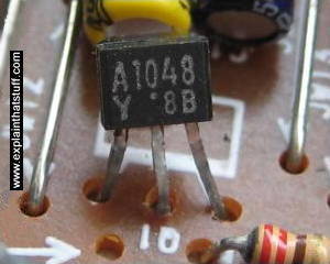
Photo: A typical transistor mounted on a circuit board.
Technically, it's an A1048 designed for use in audio-frequency amplifiers.
It has three connections, the base, collector, and emitter (though it's hard to tell which is which from this photo). Hundreds, thousands, or even millions of these are built into tiny chips called integrated circuits.
As we've already seen, there's a limit to how much an amplifier will boost a signal
without clipping or distortion. One way to get around this is to connect more than one
amplifier together so the output from one feeds into the next one's
input—and so on, in a chain, until you get as much of a boost as you
need. Devices that work like this are called multistage
amplifiers.
Some types of audio equipment use two separate amplifiers—a pre-amplifier
("pre-amp") and a main amplifier. The pre-amplifier takes the
original signal and boosts it to the minimum input level that the
main amplifier can handle. The main amplifier then boosts the signal
enough to power loudspeakers. Such things as record-player turntables
and MP3 players (played through big stereo equipment) typically need
pre-amplifiers.
Do amplifiers make energy?
Whichever kind of amplifier you use, you never get out more energy than you put in.
It's true that the output current or voltage may be many times bigger
than the input signal, but that doesn't mean you're generating extra
energy for free—a basic law of physics called the
conservation of energy doesn't allow such things.
So how come something like an electric guitar amplifier puts out more sound than it takes in?
Isn't that creating energy? No! An amplifier almost always uses an external power supply of some sort and that accounts for the difference between the energy you get out and the energy you put in: the "extra" energy is
coming from the power supply.
Think about a typical hearing aid. There's much more sound energy
coming out of its loudspeaker than there is going into its
microphone, but that doesn't mean it's making energy out of thin air.
The transistor (or integrated circuit chip) that's amplifying the
input signal has to be powered by batteries, and that's where the
extra energy is coming from. Similarly, with an electric guitar: you
have to plug the amplifier into an electrical outlet before you hear
any sound.
Artwork: Amplifiers don't make energy. Like everything else in the universe, they obey the law of conservation of energy. With a guitar amplifier, the total energy it gives out (2) is equal to any energy
it gets from your guitar (1) plus whatever energy it gets from its power supply (3), minus any energy it wastes
as heat. So although it looks like you're changing a small amount of energy (1) into a bigger amount (2),
the energy you supply from (3) explains the discrepancy; energy books always balance.
Alas, there's no such thing as energy for free—"extra" energy
always has to come from somewhere.
Even with Shockley's mule, energy isn't being created out of thin air:
the difference in energy between the match you strike and the bucking
mule comes from the food the mule must have consumed beforehand!
Sponsored links
Types of amplifiers
Photo: Amplifiers aren't always electrical. Before the invention of electronic hearing aids, ear trumpets were widely used by the hard of hearing to amplify sounds. They collect sound energy over a large area and
funnel it into a much smaller area, so making it sound louder—that's simple, mechanical amplification. Exactly the same idea was used by the military to listen out for approaching enemy aircraft. In this photo from 1921, you can see an
airman (red) at Bolling Field airbase using two gigantic ear trumpets (blue) pointed at the horizon.
These days we use radar instead.
Photo by National Photo Company courtesy of
US Library of Congress.
If amplifiers have only one simple job to
do—making a signal bigger while distorting it as little as
possible—you might think one type of amplifier would be plenty.
After all, how many different ways can you make something bigger? In
fact, as a quick online search will reveal, there are zillions of
different kinds of amplifier, they come in all shapes and sizes (from
single transistors used in hearing aids right up to gigantic audio
amps used to power loudspeakers at rock concerts) and we can classify
them in many different ways. We could, for example, sort them by what
they do for us (boosting radio signals, perhaps, or making the
signals from a record-player pickup loud enough to push a loudspeaker
back and forth) or how they do it (how their circuits are wired up
inside); whether they work in an analog way or using digital
circuits; whether they're used alone or in sequence with other
amplifiers; how much gain they give to our signal or how efficiently
they use power; and even by what sorts of components they're built
from (vacuum tubes, transistors, or integrated circuits). With so many
different factors to think about, amplifiers can be very confusing
when you first encounter them; let's try to make sense of them all
the same.
Classed by voltage, current, and power
Every amplifier takes in some kind of input signal
(a certain current and voltage, which, together multiply to give a
certain power level) and produces a bigger output signal (which may have a
different current, voltage, or power). One very basic classification
we can make is between voltage and power amplifiers. In a voltage
amplifier, the output voltage is always bigger than the input voltage
(so there's a voltage gain), although that doesn't necessarily mean
there's also a gain in power (because the current could be reduced at
the same time). In a power amplifier, the output power is always
bigger than the input power because the product of the output voltage
and output current (the output power) is bigger than the product of
the input voltage and input current (the input power).
Amplifiers aren't always designed to turn a small
voltage or power level into a bigger one; sometimes it's the current
we're interested in instead. With conventional amplifiers, the gain
we're interested in is defined as the ratio of the output voltage to
the input voltage (or the output current to the input current).
Sometimes, however, we want an amplifier to produce an output current
that's proportional to our input voltage; for that job, we'd
use what's called a transconductance amplifier. A transresistance
amplifier does the opposite job (producing an output voltage
proportional to the input current).
Classed by frequency
From crackly radio signals zapping through the air
to scratchy sounds scraped from the face of an LP,
amplifiers usually boost not a constant voltage or current but a
fluctuating signal of some kind. By fluctuating, we mean that
it changes at a certain frequency (so many times per second, measured
as so many hertz, Hz). Audio signals (ones we can hear), for example,
change in the broad frequency range from about 20 Hz to 20,000 kHz
(the sound range young, keen human ears can detect); radio signals
fluctuate thousands of times faster (in the range from kilohertz to
megahertz); and video signals (used in TV broadcasting) cover a wide
band of frequencies, equivalent to running from the very low audio (a few hertz)
right up to the very high radio (many megahertz). Because of the way
amplifiers are designed, they invariably work better at some
frequencies than others. That means that an amplifier designed to
faithfully boost audio signals is unlikely to work as effectively
with radio or video signals—and vice-versa.
Photo: This electronic hearing aid from the 1950s–1960s (shown here with its case open) is essentially a pocket audio amplifier: the four black transistors on the left do the amplifying. All we're interested in amplifying here are audible sound frequencies. Early hearing aids amplified all frequencies by the same amount; modern aids can be tuned to give more selective amplification of particular frequencies to match a person's precise pattern of hearing loss.
Classes A–D
No amplifier is perfect in every respect or
perfectly suited for every application; there are many different
applications for amplifiers and many different types available. When
you choose an amplifier for a particular application, you're always
compromising on something—either gain (how much of a boost you get),
linearity (how closely the output signal resembles the input, often
informally referred to as "fidelity," especially for audio
amplifiers), or efficiency (how much power you waste during the
amplification process). Apart from being classified by things like
voltage, power, current, and frequency, or their end-use, amplifiers
are often also classified using letters of the alphabet (typically A
to D), which, broadly speaking, tell you whether a certain amplifier
is optimized for linearity, efficiency, or a compromise between them
both.
Class A amplifiers generally provide the best
output quality (the best linearity), but tend to be large, hot,
heavy, power-hungry, and inefficient. Class B offer poorer linearity
but are cheaper, run cooler, and are much more efficient. Class AB
are a compromise solution, aiming for the output quality of class A
and the efficiency of class B. Class C amplifiers have much higher
efficiency but much poorer output quality. You'll also sometimes see
other amplifier classes (D, F, G, H, I, S, and T), though we'll not
go into those any further here.
Photo: And, yes, if you want a guitar amp but you can't afford one, there's an app for it. This one's AmpKit, a "virtual amplifier" that runs on your iPhone. Simply plug in your guitar, download your choice of amps, pedals, cabinets, and mikes, and off you go. Here I'm simulating a Peavey ValveKing on an iPod Touch, but this app offers lots of others to choose from.
Classed by construction
Does it really matter how an amplifier is made if
it boosts your signal? To many people, the answer is a very
resounding "yes." Hi-fi buffs often swear by old-style
vacuum-tube ("valve") amplifiers, which they insist give a
"warm," hi-fidelity sound, though inevitably much comes down to
personal preference. Vacuum tubes might be great if your objective is to
drive a pair of classy speakers with an expensive turntable, but
they're no use whatsoever if you're deaf and you want a small,
discreet, but still highly accurate hearing-aid. Back in the 1950s
and 1960s, transistors revolutionized hearing-aid technology but did
little more than boost signals from a microphone (amplifying all the
input equally, so making background noise worse as well as the sounds
you really wanted to hear); from the 1980s onward, digital hearing
aids used much more complex integrated circuits to provide more
selective amplification of signals, without noise, tailored precisely
to each person's specific pattern of hearing loss. In other words, it
matters very much how an amplifier's constructed.
Other special amplifiers
Amplifiers aren't always designed to carry out
simple, straightforward signal boosting. Operational amplifiers
("op-amps"), for example, are common components in electronic
circuits that can be used for all kinds of things, from basic
computing operations like addition and subtraction to signal
filtering and oscillation.
Who invented amplifiers?
Although he liked to refer to himself as the
"father of radio," American physicist and electronics engineer
Lee de Forest might be better described as the "father of the
amplifier."
In the early years of the 20th century, he
was working in radio ("wireless telegraphy" as it was then often
called) and had filed a couple of dozen patents on improved antennas
and receivers. On October 25, 1906, he filed a patent for a "device
for amplifying feeble electrical currents": a compact, electron
vacuum tube called the Audion, later known as the triode (because, in
its final version, it had three key electrical components inside). Although de
Forest originally imagined the triode as a telephone-circuit
amplifier, it eventually became an essential component of radio receivers. Despite
inventing the Audion, de Forest neither perfected it nor ever really
understood how it worked (the two things may well have been connected); it was left to others
(notably Irving Langmuir of General Electric and Edward Armstrong, inventor of FM radio) to turn the idea
into a practical device and explain the physics behind it.
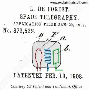
Artwork: An original sketch of Lee de Forest's
Audion (triode) vacuum tube from one of his later patents, US Patent 879,532: Space Telegraphy, filed January 29, 1907 and granted on
February 18, 1908. from which this artwork is taken, courtesy of the US Patent and Trademark Office.
How, then, does it work? The sealed glass vacuum
tube (shaded gray and labeled D, from which all the air has been
pumped out) has three key components inside, which I've colored red,
blue, and green. On the left, there's a wire filament (red, F) heated
by a battery. This is the cathode or negative terminal. On the right,
there's a platinum plate (green, b), which is the positive terminal.
In between them, there's a grid of platinum wire (blue, a). When the
filament is heated, negatively charged electrons boil off it and are
pulled toward the positively charged plate, making an electric
current flow. A negative voltage is also applied to the grid,
effectively "braking" the flow of electrons. Because the grid is
so close to the filament, even tiny changes to its voltage will make
a huge difference to the current that flows from the filament to the
plate. If we consider the grid to be the amplifier's input, the
cathode-plate circuit is its output; a small signal applied to the
grid can become a much larger, amplified signal at the plate.
Vacuum tubes based on the triode made splendid
amplifiers, but they were large, unreliable, and power-hungry. When
John Bardeen, Walter Brattain, and William Shockley developed their
"solid-state" transistor in 1947, they solved all three problems
at a stroke, making possible small, portable, highly reliable
amplifiers for such things as hearing aids and transistor radios.
When integrated circuits were invented, in the late 1950s, they led
to smaller, more complex amplifier circuits packaged as single chips
(as op-amps typically are now).
Just Don't Call Them Hearing Aids by Anne Eisenberg. The New York Times, March 22, 2014. New in-ear amplifiers promise a sound boost for people who struggle to hear in noisy places but aren't yet ready for hearing aids.
The iPod and the Vacuum Tube Sing a Warm Duet by Anne Eisenberg. The New York Times, April 15, 2007. Explores docking-station valve amplifiers for iPods, such as the Fatman iTube and Cocoon MC4.
Please do NOT copy our articles onto blogs and other websites
Articles from this website are registered at the US Copyright Office. Copying or otherwise using registered works without permission, removing this or other copyright notices, and/or infringing related rights could make you liable to severe civil or criminal penalties.