Measuring electricity is really easy—we're
all familiar with electrical units like volts, amps, and watts (and most of us have seen
moving-coil meters
in one form or another). Measuring magnetism is a little bit harder. Ask most
people how to measure the strength of a magnetic field (the invisible
area of magnetism extending out around a magnet) or the units in
which field strength is measured (webers or teslas, depending on how
you're measuring) and they wouldn't have a clue.
But there's a simple way to measure magnetism with a device
called a Hall-effect sensor or probe, which uses a clever bit of
science discovered in 1879 by American physicist
Edwin H. Hall
(1855–1938). Hall's work was ingenious and years ahead of its time—20 years
before the discovery of the electron—and no-one really knew what to do with it until decades later when semiconducting materials such as silicon became better understood. These days, Edwin Hall would be delighted
to find sensors named for him are being used in all
kinds of interesting ways. Let's take a closer look!
Photo: A Hall-effect sensor (indicated by the white arrow) helps to measure the rotational position of this old floppy disk motor. More about this in a moment...
Working together, electricity and magnetism can make things move:
electric motors, loudspeakers, and
headphones are just a few of the indispensable
modern gadgets that function this way. Send a fluctuating electric
current through a coil of copper wire and (although you can't see it
happening) you'll produce a temporary magnetic field around the coil
too. Put the coil near to a big, permanent magnet and the temporary
magnetic field the coil produces will either attract or repel the
magnetic field from the permanent magnet. If the coil is free to
move, it will do so—either toward or away from the permanent magnet. In an
electric motor, the coil is set up so it can spin around on the spot
and turn a wheel; in loudspeakers and
headphones, the coil is glued
to a piece of
paper, plastic, or
fabric that moves back and forth to
pump out sound.
Photo: You can't see a magnetic field, but you can measure it with the Hall effect. Photo by
courtesy of Wikimedia Commons.
“If the current of electricity in a fixed conductor is
itself attracted by a magnet, the current should be drawn to one side of the wire...”
Edwin Hall, 1879
What if you place a piece of current-carrying wire in a magnetic field and the wire
can't move? What we describe as electricity is generally a flow of
charged particles through crystalline (regular, solid) materials (either negatively charged electrons, from inside atoms, or sometimes positively charged "holes"—gaps where electrons should be).
Broadly speaking, if you hook a slab of a conducting material up to a battery,
electrons will march through the slab in a straight line. As moving electric charges,
they'll also produce a magnetic field. If you place the slab between
the poles of a permanent magnet, the electrons will deflect into a
curved path as they move through the material because their own
magnetic field will be interacting with the permanent magnet's field.
(For the record, the thing that makes them deflect is called the
Lorentz force, but we don't need to go into all the details here.)
That means one side of the material will see more electrons than the
other, so a potential difference (voltage) will appear across the
material at right angles to both the magnetic field from the
permanent magnet and the flow of current. This is what physicists call the Hall effect.
The bigger the magnetic field, the more the electrons are deflected; the bigger the current,
the more electrons there are to deflect. Either way, the bigger the
potential difference (known as the Hall voltage) will be. In other
words, the Hall voltage is proportional in size to both the electric
current and the magnetic field. All this makes more sense in
our little animation, below.
How does the Hall effect work?
When an electric current flows through a material, electrons (shown here as blue blobs) move through it in pretty much a straight line.
Put the material in a magnetic field and the electrons inside it are in the field too. A force acts on them (the Lorentz force) and makes them deviate from their straight-line path.
Now looking from above, the electrons in this example would bend as shown: from their point of view, from left to right. With more electrons on the right side of the material (the bottom in this picture) than on the left (the top in this picture), there would be a difference in potential (a voltage) between the two sides, as shown by the green arrowed line. The size of this voltage is directly proportional to the size of the electric current and the strength of the magnetic field.
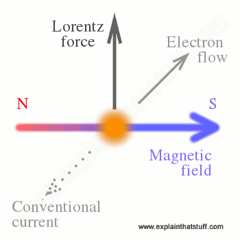
Which way do they go?
How do you figure out which way the electrons will move? You can work out the direction of the Lorentz force with Fleming's left-hand rule (if you correct for conventional current) or his right-hand rule (if you don't).
Artwork: Charged particles moving in a magnetic field experience a force (the Lorentz force) that changes their direction, giving rise to the Hall effect. You can use Fleming's left-hand rule (motor rule) to figure out the direction of the force providing you remember that the rule applies to conventional current (a flow of positive charges) and the field flows from north to south. In this example, if we have a flow of electrons into the page, the conventional current flows out of the page (so that's the direction in which your second finger should point). If the field flows from left to right (first finger), our thumb tells us the electrons will move upward.
Sponsored links
Using the Hall effect
You can detect and measure all kinds of things with the Hall-effect using what's known
as a Hall-effect sensor or probe. These terms are sometimes used
interchangeably but, strictly speaking, refer to different things:
Hall-effect sensors are simple, inexpensive,
electronic chips that are used
in all sorts of widely available gadgets and products.
Hall-effect probes are more expensive and sophisticated instruments used
in scientific laboratories for things like measuring magnetic field strength with very high precision.
Photo: 1) A typical silicon Hall-effect sensor. It looks
very much like a transistor—hardly surprising since it's made in a similar way.
Photo by explainthatstuff.com. 2) A Hall-effect probe used by NASA in the mid-1960s. Photo by courtesy of
NASA Glenn Research Center (NASA-GRC).
Typically made from semiconductors (materials such as silicon and germanium), Hall-effect
sensors work by measuring the Hall voltage across two of their faces
when you place them in a magnetic field. Some Hall sensors are
packaged into convenient chips with control circuitry and can be
plugged directly into bigger electronic circuits. The simplest way of
using one of these devices is to detect something's position. For
example, you could place a Hall sensor on a door frame and a magnet
on the door, so the sensor detects whether the door is open or closed
from the presence of the magnetic field. A device like this is called
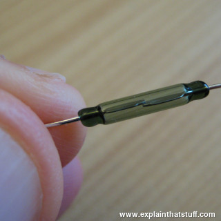
a proximity sensor. Of course, you can do the same job just as easily
with a magnetic reed switch
(there is no general rule as to whether
old-style reed switches or modern, Hall-effect sensors are better—it
depends on the application). Unlike reed switches, which are mechanical and rely on contacts
moving in a magnetic field, Hall sensors are entirely electronic and have no moving parts, so
(theoretically, at least) they should be more reliable. One thing you can't do with a reed switch is detect degrees of "on-ness"—the strength of the magnetism—because a reed switch is either on or off. That's what makes a Hall-effect sensor so useful.
What are Hall-effect sensors used for?
Hall-effect sensors are cheap, robust and reliable, tiny, and easy to use,
so you'll find them in lots of different machines and everyday devices,
from car ignitions to computer keyboards and factory robots to exercise bikes.
Here's one very common example you might be using in your computer right now. In a
brushless DC motor (used in such things as hard- and floppy-disk drives), you need to be able to sense exactly where the motor is positioned at any time. A Hall-effect sensor
stationed near the rotor (rotating part of the motor) will be able to
detect its orientation very precisely by measuring variations in the
magnetic field. Sensors like this can also be used to measure speed
(for example, to count how fast a wheel or car enginecam or crankshaft is rotating). You'll often find
them in electronic speedometers
and anemometers (wind-speed meters), where they can be used
in a similar way to reed switches.
Photo: This small brushless DC motor from an old floppy-disk drive has three Hall-effect sensors
(indicated by red circles) positioned around its edge, which detect the motion of the motor's rotor (a rotating permanent magnet) above them (not shown on this photo). The sensors are not much to look at, as you can see from the closeup photo on the right!
It took a few decades for Edwin Hall's revolutionary discovery to catch on, but now it's
used in all kinds of places—even in electromagnetic space rocket engines.
It's no exaggeration to say that Hall's groundbreaking work has had quite an effect!
Artwork: How a typical Hall sensor is packaged. Magnetic fields can be very small, so we need our detectors to be as sensitive as possible, and here's one way to achieve that. The Hall chip itself (green, 17) is mounted on an iron carrier plate (gray, 16) sandwiched inside two molded plastic sections (gray, 11, 12). The chip is wired by leads (19) to terminal pins (blue) by which it can be connected into a circuit. But the really important parts are two soft iron "flux concentrators" (orange, 15, 21), which make the device very much more sensitive. When you place a magnet (22) near the sensor, these concentrators allow the magnetic flux (the "density" of magnetism produced by the magnetic field) to flow around a continuous loop through the Hall chip, producing either a positive or negative voltage. If the magnet slides over to the other side of the sensor, it produces the opposite voltage. Artwork from US Patent 3,845,445: Modular Hall Effect Device by Roland Braun et al, IBM Corporation, October 29, 1974, courtesy of US Patent and Trademark Office.
Sponsored links
Don't want to read our articles? Try listening instead
How Do You Measure the Magnetic Field? by Rhett Allain. Wired, January 21, 2014. Comparing traditional compasses with Hall-effect sensors found in a smartphone.
[PDF] The discovery of the Hall effect by G.S. Leadstone, Physics Education, Volume 14, 1979. How Hall discovered his effect and figured out what it meant by challenging some of the earlier work by James Clerk Maxwell.
More technical
The Vertical Hall-Effect Device by R. S. Popovic, IEEE Electron Device Letters, Vol.5, No.9, pp.357–358, Sept. 1984, doi: 10.1109/EDL.1984.25945.
An Explanation of Hall's Phenomenon by Edwin H. Hall,
Science, Vol. 3, No. 60 (Mar. 28, 1884), pp. 386–387. Hall's own description and explanation of his original experiment.
Hall-Effect Sensors: Theory and Applications by Edward Ramsden. Newnes, 2006. Covers the physics behind Hall-effect sensors and how to incorporate them into practical circuits. Includes coverage of proximity sensors, current-sensors, and speed-and-timing sensors. Also has a handy glossary and list of suppliers.
Hall-Effect Devices by R. S. Popović. Institute of Physics, 2004. A somewhat bigger and more detailed book, but covering similar ground with a mixture of theory, practical circuits, and everyday applications.
The Hall Effect and Its Applications by C. Chien (ed). Plenum Press, 1980/Springer, 2013. A reissue of the proceedings of a 1979 symposium at Johns Hopkins University, on November 13, 1979 to commemorate the 100th anniversary of Hall's discovery.
Please do NOT copy our articles onto blogs and other websites
Articles from this website are registered at the US Copyright Office. Copying or otherwise using registered works without permission, removing this or other copyright notices, and/or infringing related rights could make you liable to severe civil or criminal penalties.