Imagine holding out your hand and catching words, pictures, and
information passing by. That's more or less what an antenna
(sometimes called an aerial) does: it's the metal rod or dish that
catches radio waves and turns them into electrical signals feeding
into something like a radio or
television or a telephone system.
Antennas like this are sometimes called receivers. A transmitter is a
different kind of antenna that does the opposite job to a receiver:
it turns electrical signals into radio waves so they can travel
sometimes thousands of kilometers around the Earth or even into space
and back. Antennas and transmitters are the key to virtually all
forms of modern telecommunication. Let's take a closer look at what
they are and how they work!
Photo: A truck-mounted satellite dish antenna.
Photo by courtesy of NASA Glenn Research Center and Internet Archive.
Suppose you're the boss of a radio station and you want to
transmit your programs to the wider world. How do you go about it?
You use microphones to capture the sounds of people's voices and turn
them into electrical energy. You take that electricity and, loosely
speaking, make it flow along a tall metal antenna (boosting it in
power many times so it will travel just as far as you need into the world). As the
electrons (tiny particles inside atoms) in the electric current wiggle back and forth along the
antenna, they create invisible electromagnetic radiation in the form of radio
waves. These waves, partly electric and partly magnetic, travel out at the speed of light, taking your radio
program with them. What happens when I turn on my radio in my home a
few miles away? The radio waves you sent flow through the metal antenna
and cause electrons to wiggle back and forth. That generates an
electric current—a signal that the electronic components inside my
radio turn back into sound I can hear.
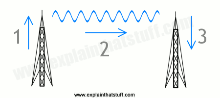
Artwork: How a transmitter sends radio waves to a receiver. 1) Electricity flowing into the transmitter antenna makes electrons vibrate up and down it, producing radio waves. 2) The radio waves travel through the air at the speed of light. 3) When the waves arrive at the receiver antenna, they make electrons vibrate inside it. This produces an electric current that recreates the original signal.
Transmitter and receiver antennas are often very similar in
design. For example, if you're using something like a satellite phone
that can send and receive a video-telephone call to any other place
on Earth using space satellites, the signals you transmit and receive
all pass through a single satellite dish—a special kind of antenna
shaped like a bowl (and technically known as a parabolic reflector,
because the dish curves in the shape of a graph called a parabola).
Photo: A parabolic reflector dish (1) catches incoming waves and bounces them up to
a much smaller, concentrating "subreflector" above and in the center of the dish (2), from which they're
reflected down for processing (3). A dish like this can also work as a transmitter, simply by sending
radio beams in the opposite direction. Deep Space Network antenna photo courtesy of
NASA.
Waves don't always zap through the air from transmitter to receiver. Depending on what kinds (frequencies) of waves we want to send, how far we want to send them, and when we want to do it, there are actually three different ways in which the waves can travel: 1) By line of sight; 2) By ground wave; 3) Via the ionosphere.
Artwork: How a wave travels from a transmitter to a receiver: 1) By line of sight; 2) By ground wave; 3) Via the ionosphere.
As we've already seen, they can shoot by what's called "line of sight", in a straight line—just like a beam of light. In old-fashioned long-distance telephone networks, microwaves were used to carry calls this way between very high communications towers
(fiber-optic cables have largely made this obsolete).
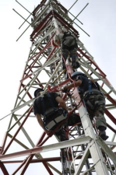
Photo: Antennas that use line-of-sight communication need to be mounted on high towers, like this. You can see the thin dipoles of the antenna sticking out of the top, but most of what you see here is just the tower that holds the antenna high in the air. Photo by Pierre-Etienne Courtejoie courtesy of US Army.
They can speed round the Earth's curvature in what's known as a ground wave. AM (medium-wave) radio tends to travel this way for short-to-moderate distances. This explains why we can hear radio signals beyond the horizon (when the transmitter and receiver are not within sight of each other).
They can shoot up to the sky, bounce off the ionosphere (an electrically charged part of Earth's upper atmosphere), and come back down to the ground again. This effect works best at night, which explains why distant (foreign) AM radio stations are much easier to pick up in the evenings. During the daytime, waves shooting off to the sky are absorbed by lower layers of the ionosphere. At night, that doesn't happen. Instead, higher layers of the ionosphere catch the radio waves and fling them back to Earth—giving us a very effective "sky mirror" that can help to carry radio waves over very long distances.
Sponsored links
How long does an antenna have to be?
The simplest antenna is a single piece of metal wire attached to a
radio. The first radio I ever built, when I was 11 or 12, was a
crystal set with a long loop of copper wire acting as the antenna. I ran the
antenna right the way around my bedroom ceiling, so it must have been
about 20–30 meters (60–100 ft) long in all!
Most modern transistor radios have at least two antennas. One of
them is a long, shiny telescopic rod that pulls out from the case and
swivels around for picking up FM (frequency modulation) signals. The
other is an antenna inside the case, usually fixed to the main
circuit board, and it picks up AM (amplitude modulation) signals.
(If you're not sure about the difference between FM and AM, refer to our radio article.)
Why do you need two antennas in a radio? The signals on these
different wave bands are carried by radio waves of different
frequency and wavelength. Typical AM radio signals have a frequency
of 1000 kHz (kilohertz), while typical FM signals are about 100 MHz
(megahertz)—so they vibrate about a hundred times faster. Since all radio
waves travel at the same speed (the speed of light, which is 300,000
km/s or 186,000 miles per second), AM signals have
wavelengths about a hundred times bigger than FM signals. You need two
antennas because a single antenna can't pick up such a hugely
different range of wavelengths. It's the wavelength (or frequency, if
you prefer) of the radio waves you're trying to detect that
determines the size and type of the antenna you need to use. Broadly speaking,
the length of a simple (rod-type) antenna has to be about half the wavelength of the
radio waves you're trying to receive (it's also possible to make
antennas that are a quarter of the wavelength, compact miniaturized antennas that are about a tenth the wavelength,
and membrane antennas that are even smaller, though we won't go into that here).
The length of the antenna isn't the only thing that affects the wavelengths
you're going to pick up; if it were, a radio with a fixed length of antenna
would only ever be able to receive one station. The antenna feeds signals into a tuning circuit
inside a radio receiver, which is designed to "latch onto" one particular frequency and ignore the rest.
The very simplest receiver circuit (like the one you'll find in a crystal radio)
is nothing more than a coil of wire, a
diode, and a capacitor, and it feeds sounds into an earpiece.
The circuit responds (technically, resonates, which means electrically oscillates) at the frequency you're tuned into
and discards frequencies higher or lower than this. By adjusting the value of the capacitor,
you change the resonant frequency—which tunes your radio to a different station.
The antenna's job is to pick up enough energy from passing radio waves to make the
circuit resonate at just the right frequency.
AM and FM antennas: the long and short of it
Let's see how it works for FM. If I try to listen to a typical
radio broadcast on an FM frequency of 100 MHz (100,000,000 Hz), the
waves carrying my program are about 3m (10ft) long. So the ideal
antenna is about 1.5m (4ft) or so long, which is roughly the
length of a telescopic FM radio antenna when it's fully extended.
Photo: The AM "loopstick" antenna inside a typical transistor radio
is very compact and highly directional. The pink-colored wire that makes up the antenna is wrapped around a thick ferrite core (the black rod). Usually, as you can see here, there are two separate antennas on the same ferrite rod: one for AM (medium-wave) and one for LW (long-wave).
Now for AM, the wavelengths are about 100 times greater, so how come you don't
need an antenna that's 300m (0.2 miles) long to pick them up?
Well you do need a powerful antenna, you just don't know it's there!
The AM antenna on the inside of a transistor radio works in a very different
way to the FM antenna on the outside.
Where an FM antenna picks up the electric part of a radio wave,
an AM antenna couples with the magnetic part instead.
It's a length of very thin wire (typically
several tens of meters) looped anything from a few dozen to a few hundred times around a ferrite (iron-based magnetic) core, which greatly concentrates the magnetic part of the radio signals and produces ("induces") a bigger current in the wire wrapped around them.
That means an antenna like this can be really tiny and still pack a punch.
Without the ferrite rod, a loop antenna either needs many more turns of wire
(so thousands instead of hundreds or dozens) or the loops of wire
need to be a lot bigger. That's why external antennas for radio sets sometimes take
the form of a big loop, maybe 10–20cm (4–8in) in diameter or so.
Artwork: Top: Electromagnetic radio waves consist of vibrating electric waves (blue) and magnetic waves (red) traveling together at the speed of light (black arrow). Bottom: Left: An FM antenna picks up the relatively short wavelength, high-frequency electric part of FM radio waves. Right: An AM ferrite loop antenna picks up and concentrates the magnetic parts of longer wavelength, lower frequency electromagnetic waves.
So far so good, but what about cellphones? How come they need only short and stubby
antennas like the one in this photo? Cellphones use radio waves too, also traveling at the speed of light,
and with a typical frequency of 800 MHz (roughly ten times greater than FM radio).
That means their wavelength is about 10 times shorter than FM radio, so they need
an antenna roughly one tenth the size. In smartphones, typically the antenna stretches
around the inside of the case. Let's see how that computes: if the
frequency is 800MHz, the wavelength is 37.5cm (14.8in), and half the wavelength would
be 18cm (7.0in). My current LG smartphone is about 14cm (5.5in) long, so you can see
we're in the right sort of ballpark.
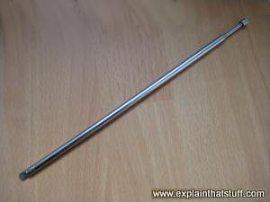
Photo: 1) This telescopic FM radio antenna pulls out to a length of about 1–2m (3–6ft or so), which is roughly half the length of the radio waves it's trying to capture. 2) Cellphones have particularly compact antennas. Older ones (like the Motorola on the left) have stubby external antennas or ones that pull out telescopically.
(The exposed part of the antenna is the bit my finger is pointing to and
there's another part we can't see running around the edge of the circuit board inside the case.)
Newer cellphones (like the Nokia model on the right) have longer antennas built completely inside the case.
More types of antennas
The simplest radio antennas are just long straight rods, sometimes called
monopoles. Many indoor TV antennas take the form of a dipole: a metal rod split into two pieces and
folded horizontally so it looks a bit like a person standing straight
up with their arms stretched out horizontally.
Photos: A "bowtie antenna" (held by the man on the left) is a variation
on a basic dipole. The diagonally angled wires help it to pick up a wider range of frequencies, which is why
small bowties were often used indoors with basic TV sets (to pick up a good selection of channels).
Photo by Andrew Ochoa courtesy of US Marine Corps and
DVIDS.
More sophisticated outdoor
TV antennas have a number of these dipoles arranged along a central
supporting rod. Other designs include circular loops of wire and, of
course, parabolic satellite dishes. Why so many different designs?
Obviously, the waves arriving at an antenna from a transmitter are exactly the same, no matter what
shape and size the antenna happens to be. A different pattern of dipoles will help to concentrate the signal so it's easier to detect. That effect can be increased even more by adding unconnected, "dummy" dipoles, known as directors and reflectors, which bounce more of the signal over to the actual, receiving dipoles. This is equivalent to boosting the signal—and being able to pick up a weaker signal than a simpler antenna.
Artwork: Four common types of antenna (red) and the places where they pick up best (orange): A basic dipole, a folded dipole, a dipole and reflector, and a Yagi. A basic or folded dipole antenna picks up equally well in front of or behind its poles, but poorly at each end. An antenna with a reflector picks up much better on one side than the other, because the reflecting element (the red, dipole-like bar on the left) bounces more signal over to the folded dipole on the right. The Yagi exaggerates this effect even more, picking up a very strong signal on one side and almost no signal anywhere else. It consists of multiple dipoles, reflectors, and directors.
Sponsored links
Important properties of antennas
Three features of antennas are particularly important, namely their directionality, gain, and bandwidth.
Directionality
Dipoles are very directional: they pick up incoming radio waves traveling at
right angles to them. That's why a TV antenna has to be properly
mounted on your home, and facing the correct way, if you're going to
get a clear picture. The telescopic antenna on an FM radio is less
obviously directional, especially if the signal is strong: if you
have it pointed straight upward, it will capture good signals from
virtually any direction. The ferrite AM antenna inside a radio is
much more directional. Listening to AM, you'll find you
need to swivel your radio around until it picks up a really strong
signal. (Once you've found the best signal, try turning your radio through exactly 90 degrees and notice how the
signal often falls off almost to nothing.)
Photo: Directionality: Dipole antennas like this are highly directional.
Here, the antenna is being used to track tortoises in the desert for a
conservation project. Photo by Dave Flores courtesy of US Marine Corps and
DVIDS
.
Although highly directional antennas
may seem like a pain, when they're properly aligned, they help to reduce
interference from unwanted stations or signals close to the one you're trying
to detect. But directionality isn't always a good thing. Think about your cellphone.
You want it to be able to receive calls wherever it is in relation to the
nearest phone mast, or pick up messages whichever way it happens to be pointing when it's
lying in your bag, so a highly directional antenna isn't much good.
Similarly for a GPS receiver that tells you where you are
using signals from multiple space satellites. Since the signals come from different
satellites, in different places in the sky, it follows that they come from different directions, so, again,
a highly directional antenna wouldn't be that helpful.
Gain
The gain of an antenna is a very technical measurement but,
broadly speaking, boils down to the amount by which it boosts the
signal. TVs will often pick up a poor, ghostly signal even without an
antenna plugged in. That's because the metal case and other
components act as a basic antenna, not focused in any particular
direction, and pick up some kind of signal by default. Add a proper
directional antenna and you'll gain a much better signal.
Gain is measured in decibels (dB), and (as a broad rule of thumb) the bigger the gain
the better your reception. In the case of TVs, you get much more gain from a complex
outdoor antenna (one with, say, 10–12 dipoles in a parallel "array") than from a simple dipole.
All outdoor antennas work better than indoor ones, and window and set-mounted antennas
have higher gain and work better than built-in ones.
Photo: Gain: The Apollo 17 mission's lunar rover (pictured here on the Moon in December 1972) carried a high-gain, foldable parabolic-reflector antenna (top right) that resembled an umbrella. Photo courtesy of
NASA.
Bandwidth
An antenna's bandwidth is the range of frequencies (or
wavelengths, if you prefer) over which it works effectively. The
broader the bandwidth, the greater the range of different radio
waves you can pick up. That's helpful for something like television,
where you might need to pick up many different channels, but much
less useful for telephone, cellphone, or satellite communications
where all you're interested in is a very specific radio wave
transmission on a fairly narrow frequency band.
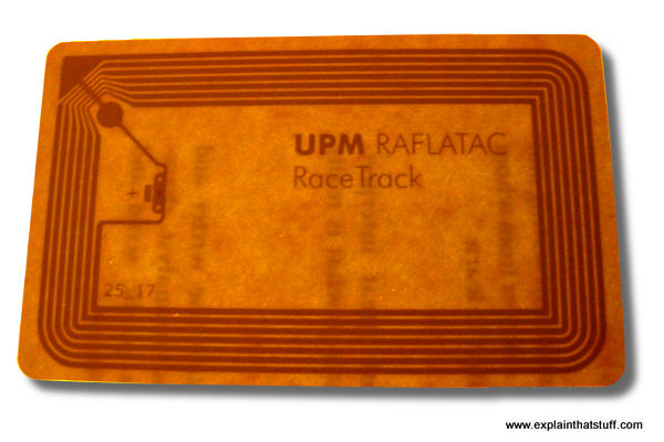
Photos: Bandwidth. Mobile devices typically use compact microstrip antennas (printed directly onto circuit boards) designed to work at very limited, specific frequencies, so they tend to have a narrow bandwidth. 1) The antenna that powers an RFID tag stuck inside a library book. The circuit inside it has no power source: it gets all its energy from the incoming radio waves,
typically 13.56MHz (per the International Standard ISO 18000). 2) The dipole antenna inside a PCMCIA wireless Internet Wi-Fi card. This one works with 2.4GHz radio waves of wavelength 12.5cm, which is why it only needs to be about 6cm long or so in total.
Who invented antennas?
There's no easy answer to that question because radio evolved into a useful
technology through the second half of the 19th century thanks to the work of quite a
few different people—both theoretical scientists and practical experimenters.
Photo: The largely forgotten radio pioneer Sir Oliver Lodge (1851–1940). Photo courtesy of Bain News Service and US Library of Congress.
Who were these pioneers? Scottish physicist James Clerk Maxwell figured out a theory of radio around 1864,
and Heinrich Hertz proved that radio waves really did exist about 20 years later (they were
called Hertzian waves in his honor for some time afterward). Several years later, at a meeting in Oxford, England on August 14, 1894, English physicist, Oliver Lodge, demonstrated how radio waves could be used for signalling
from one room to another in what he later described (in his 1932 autobiography) as "a very infantile kind of radio-telegraphy."
Lodge filed a US patent for "electric telegraphy" on February 1, 1898, describing apparatus for "an operator, by means of what is now known
as 'Hertzian-wave telegraphy' to transmit messages across space to any one or more of a number of different
individuals in various localities..." Unknown to Lodge at that stage, Guglielmo Marconi was carrying out his own experiments
in Italy around the same time—and ultimately proved the better showman: many people think of him as
the "inventor of radio" to this day whereas, in truth, he was only one of a group of forward-thinking people who
helped turned the science of electromagnetic waves into a practical, world-changing technology.
Artwork: Oliver Lodge's illustration of sending radio waves through space from a transmitter (red) to a receiver (blue) some distance away, taken from his 1898 patent US 609,154: Electric Telegraphy. Courtesy of US Patent and Trademark Office.
None of the original radio experiments used transmitters or receivers that we would instantly recognize today. Hertz and Lodge, for example, used a piece of equipment called a spark-gap oscillator: a couple of zinc balls attached to short lengths of copper wire with an air gap in between them. Lodge and Marconi both used Branly coherers (glass tubes packed with metal filings) for detecting the waves they'd transmitted
and received, though Marconi found them "too erratic and unreliable" and eventually designed his own detector. Armed with this new equipment,
he carried out systematic experiments into how the height of an antenna affected the distance over which he could transmit
a signal.
Antenna Engineering Handbook by John L. Volakis (ed). McGraw-Hill, 2018. A huge, definitive, theoretical and practical guide to all the common types of antenna.
Antenna Theory: Analysis and Design by Constantine A. Balanis. Wiley, 2016. A good, general, theoretical introduction aimed at physics and electrical engineering undergraduates. Not really suitable for beginners—and you will need a decent grasp of math.
Tiny Membrane-Based Antennas by Charles Q. Choi. IEEE Spectrum, 22 Aug 2017. Cutting-edge antennas can now be shrunk to 1/000 the length of the wavelength they need to pick up.
Rabbit Ears Perk Up for Free HDTV by Matt Richtel and Jenna Wortham. The New York Times, December 5, 2010. Viewers tired of cable prices are rediscovering the joys of old-fashioned antennas and free TV.
Signal boost for mobile phones: BBC News, 22 April 2008. How Oxford scientists have developed a more sophisticated cellphone antenna.
Hacking with a Pringles tube by Mark Ward, BBC News, 8 March 2002. An interesting news story explaining how hackers have used directional antennas made from Pringles tubes to break into wireless networks.
What you should know about TV antennas by Robert Hertzberg, Popular Science, December 1950. This old article from the Popular Science archives remains a very clear and relevant introduction to antenna design.
Please do NOT copy our articles onto blogs and other websites
Articles from this website are registered at the US Copyright Office. Copying or otherwise using registered works without permission, removing this or other copyright notices, and/or infringing related rights could make you liable to severe civil or criminal penalties.