
How strain gauges work
by Chris Woodford. Last updated: February 14, 2023.
Is your house in danger of falling down? Was that an earthquake? Will that airplane actually fly? These are just a few of the questions you can study with a handy little device called a strain gauge (sometimes spelled "gage"). It's a neat way of measuring how much a material changes shape when a force acts on it. Strain gauges range from the immensely simple to the fiendishly complex, but all of them are superbly useful to scientists and engineers. Let's take a closer look at how they work!
Photo: This spring dynamometer measures force using strain: the more force you apply, the more the spring stretches. Doubling the force doubles the strain, so the spring stretches twice as much.
Sponsored links

Contents
What is strain anyway?
Are you stressed? Can you feel the strain? When we talk about "stress" and "strain" in everyday life, we use the two words interchangeably. But in science and engineering, these two words have very precise and very different meanings:
Stress is a measurement of how much internal pressure a material is under when a force acts on it. The bigger the force or the smaller the area over which it acts, the more likely it is that the material is to going to deform (change shape). Just like pressure, we measure stress by dividing the force that's acting by the area it's acting over, so stress = force / area.
Strain is what happens as a result of stress. If a material is stressed by a force, it often changes shape and gets a little bit longer (if you've pulled it apart) or shorter (if you've pushed it together). The strain is defined as the change in length the force produces divided by the material's original length. So if you pull a 10cm-long piece of elastic and it stretches by 1cm, the strain is 0.1.

Artwork: The concepts of stress and strain compared. Top: Stress: If you apply a pulling force to a bar of a certain cross-sectional area, you create a certain stress. If you apply the same force to a bar half the area, you produce twice as much stress. Bottom: Strain: If you apply no force to a bar, you don't stretch it at all. Apply a certain force and you'll extend its length by a certain amount, producing a certain strain. If you apply more force so you double the extension, you'll have produced twice as much strain (assuming the material behaves in a nice, simpler, linear way).
Materials under stress
Different materials behave in very different ways under similar amounts of stress. If you subject a rubber band to stress, by pulling, it stretches accordingly; release the stress and the band returns to its previous shape. When materials go back to their original shape and size after stressing forces are removed, we say they've undergone elastic deformation; many materials behave like this, including rubber, some plastics, and many metals (which, you might be surprised to hear, are perfectly elastic when very small forces are involved). Eventually, elastic materials reach a point where they can't cope with extra stress and stretch permanently. This kind of change is called plastic deformation. (Note that the proper meaning of plastic is something that changes shape relatively easily. That's why plastics are called plastics: they are easily molded into different shapes when they are manufactured.)

Photo: NASA is using strain gauges here to measure what's happening on the inside of an airplane wing. The main photo shows a closeup; the small inset photo on the right shows a zoomed-out picture with more context. Photo by courtesy of NASA Armstrong Flight Research Center.
If you're an engineer, stresses and strains are incredibly important. If you're designing anything from a car engine or a bridge to a wind turbine or an airplane wing, you know it's going to be subject to some pretty hefty forces. Can the materials you want to use stand up to those forces? Will they deform elastically by tiny amounts and return safely to their original shape and size? Will they break apart after repeated stresses and strains through a process such as metal fatigue (where repeated deformation causes a metal to weaken and suddenly snap). Do you need to use something stronger to be on the safe side? And how exactly can you tell? You can do your calculations in the lab and try to figure it out in advance. You can even build sophisticated computer models to help you. But the sure-fire way of getting an answer to how materials are coping under pressure is to use strain gauges to measure the way they behave when real-life forces act on them.
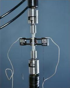
Photo: This laboratory apparatus is designed to test a material's strength by slowly pulling it apart. Strain gauges attached to the material (in this case, a piece of aluminum in the center) let scientists study the stresses and strains as it deforms. Photo by courtesy of NASA Langley Research Center (NASA-LaRC).
Types of strain gauges
There are five main types of strain gauges: mechanical, hydraulic, electrical resistance, optical, and piezoelectric. Let's compare how they work.
Mechanical
Suppose you have a crack forming in a wall of your home because of subsidence and you want to know if it's getting any worse. Call in the building inspectors and they'll probably glue a piece of tough, plexiglass plastic, ruled with lines and a scale, directly over the crack. Sometimes known as a crack monitor, you'll find it's actually made up of two separate plastic layers. The bottom layer has a ruled scale on it and the top layer has a red arrow or pointer. You glue one layer to one side of the crack and one layer to the other so, as the crack opens, the layers slide very slowly past one another and you can see the pointer moving over the scale. Depending on how quickly the crack is moving, you know how long you have to take action and resolve your problem!

Photo: A simple mechanical crack monitor. One piece (white, right) has a black two-dimensional scale marked on it; the other (transparent, left) red crosshairs. You simply watch the red crosshairs move on the scale as the crack widens. Detectors like this are made by such companies as Avongard; you can find other brands by searching for "crack monitor" on your favorite search engine or auction site. Photo by Wikimedia user RoySmith posted on Wikimedia Commons under a Creative Commons (CC BY-SA 2.5) Licence.
Some mechanical strain gauges are even more crude than this. You simply glue the piece of plastic or glass across your crack and wait for it to shatter when the building moves.
Hydraulic
One of the problems with strain gauges is detecting very small strains. You can imagine, for example, a situation where your house is slowly subsiding but the amount of movement is so small that it won't show up—perhaps until the damage is done. With a simple crack detector such as the ones described above, it takes 1mm of building movement to produce 1mm of movement on the surface of the crack detector. But what if we want to detect movements smaller than this that don't show up on a scale? In this case, what we really need is a strain gauge with leverage that amplifies the strain, so even a tiny movement of the detecting element produces a very large and easily measurable movement of a pointer over a scale.
Hydraulic detectors offer a solution and work much like simple syringes. Syringes are essentially hydraulic pistons where a small movement of fluid in a large piston (the part you press with your finger) produces a much larger movement of fluid in a small piston attached to it (the needle where the fluid comes out). It's easy to see how this can be used in a strain gauge: you simply connect your large piston to whatever it is that's producing the strain and use a smaller piston in a smaller tube, marked with a scale, to indicate how much movement has occurred. The relative size of the pistons determines how much the movement you're trying to detect is scaled up. Typically, hydraulic strain gauges like this multiply movement by a factor of 10 or so and are commonly used in geology and Earth science.

Artwork: A simple example of a hydraulic strain gauge. The strain you want to measure presses down on the green button (top left). That forces a large, wide piston (yellow, 55) into a hydraulic cylinder (red, 56), squashing trapped fluid (blue) down through a narrow pipe. This is the hydraulic principle in action: tiny movements of the green button and yellow piston are magnified into much larger movements by the narrowness of the tube. The fluid flows into a coiled-up Bourdon tube (orange, 83), which uncurls according to the pressure inside it, pulling on a lever linkage (dark blue, 84, 85), altering the overlap between a couple of induction coils so they send more or less electric current to a circuit. In this way, a force pressing on the green button is translated into a measureable electric signal. From US Patent 2,600,453: Method and apparatus for controlling heat in hot machining processes by Richard Weingart. June 17, 1952, courtesy of US Patent and Trademark Office.
Sponsored links
Electrical resistance
If you're designing something like an airplane wing, typically you need to make far more sophisticated measurements (and many more of them) than a simple mechanical strain gauge will allow. You might want to measure the strain during takeoff, for example, when the engines are producing maximum thrust. You can't go sticking little plastic strain gauges onto the wing and walk out to measure them during a flight! But you can use electrical strain gauges to do much the same thing from a flight recorder in the cockpit.

Photo: A closeup of two electrical strain gauges. You can clearly see the maze-like wiring patterns on the foil backing. These change shape, causing the wires to change resistance when the foil is bent by stresses and strains. Photo by courtesy of NASA Glenn Research Center (NASA-GRC) .
The most common electrical strain gauges are thin, rectangular-shaped strips of foil with maze-like wiring patterns on them leading to a couple of electrical cables. You stick the foil onto the material you want to measure and wire the cables up to your computer or monitoring circuit. When the material you're studying is strained, the foil strip is very slightly bent out of shape and the maze-like wires are either pulled apart (so their wires are stretched slightly thinner) or pushed together (so the wires are pushed together and become slightly thicker). Changing the width of a metal wire changes its electrical resistance, because it's harder for electrons to carry electric currents down narrower wires. So all you have to do is measure the resistance (typically using a Wheatstone bridge) and, with a bit of appropriate conversion, you can calculate the strain. If the forces involved are small, the deformation is elastic and the strain gauge eventually returns to its original shape—so you can keep making measurements over a period of time, such as during the test flight of a prototype plane.
Resistance-type strain gauges like this were invented in 1938 by MIT professor Arthur Ruge (1905–2000) to help with earthquake detection.

Artwork: Right: An illustration of Arthur Ruge's original electrical resistance strain gauge from a US patent he filed in September 1939. It consists of a conducting metal filament (yellow) stretched back and forth between a pair of comb-like supports (blue) and connected to contacts (red) that can be wired into a circuit. As the strain changes, the filament is distorted and its resistance rises or falls; measuring the resistance is a way of indirectly measuring the strain. The gauge includes a second, similar filament (orange) that can be used to compensate for any changes in resistance caused purely by changes in temperature. The idea is to choose different materials for the two filaments so that their temperature changes cancel one another out. Ruge made his filaments from strain-sensitive alloys such as Advance (copper-nickel) and Nichrome (nickel-chrome). From US Patent 2,350,972: Strain gauge by Arthur C. Ruge, June 6, 1944, courtesy of US Patent and Trademark Office.
Optical
Some materials change their optical properties (how they transmit or reflect light) when they're stressed and strained—glass and plastics are good examples. Although glass is an amazingly useful and versatile material, it's fragile and brittle, and potentially very dangerous: if it's under too great a strain, it can suddenly crack or shatter without warning. That could be a real problem in something like a plate-glass storefront window or a car windshield. One way to detect strain in glass is to shine polarized light onto it at an angle. Some of the light will be reflected and some will be transmitted; the relative amounts of transmitted and reflected light will change according to how much strain the glass is under. By measuring the amount of reflected light, we can precisely measure the strain on the glass.

Artwork: An optical strain gauge seen from the side (top) and from above (bottom), works in a similar way to a device called a polariscope (or polarimeter). It's made from two hollow tubes (gray 1,2) arranged at an angle to a piece of glass (green). A powerful light (blue, 6) shines a focused beam (yellow) down onto the glass through a polarizing filter (red, 8). According to whether the glass is strained, and by how much, some light reflects back up off the glass surface through a second filter (orange, 9) and onto a photoelectric cell (purple, 14). This converts the light into an electrical signal, making a needle rise or fall in an ammeter (dark blue, 15). The greater the strain on the glass, the more light is reflected and the higher the reading on the ammeter. From US Patent 2,119,577: Strain gauge for and method of measuring strains in glass by Samuel McK. Gray, June 7, 1938, courtesy of US Patent and Trademark Office.
Piezoelectric
Some types of materials, including quartz crystals and various types of ceramics, are effectively "natural" strain gauges. If you push and pull them, they generate tiny electrical voltages between their opposite faces. This phenomenon is called piezoelectricity (pronounced pee-ayyyy-zo electricity) and it's probably best known as a way of generating the timekeeping signal in quartz watches. Measure the voltage from a piezoelectric sensor and you can calculate the strain very simply. Piezoelectric strain gauges are among the most sensitive (about 1000 times more so than simpler types) and reliable and can withstand years of repeated use. (You'll sometimes see them called piezoelectric transducers, because they convert mechanical energy into electrical energy.)

Photo: How a piezoelectric strain gauge works. Fasten it to the object you're testing, which might be a simple steel bar (gray, 1). The sensor is a flat crystal (blue, 3), with two parallel faces that have electrodes fixed to them (colored red and orange, 4 and 5) attached to contacts (yellow, 6 and 7) that run out to an external circuit and some kind of meter. The lower face of the crystal (red) is bonded with cement (8) very firmly to the test sample. As the sample deforms, the crystal deforms too, generating a small voltage between its top and bottom faces as its shape changes. The bigger the strain, the bigger the voltage, so measuring the voltage is a very accurate way of measuring the strain. From US Patent 2,558,563: Piezoelectric strain gauge by William Janssen, General Electric, June 26, 1951, courtesy of US Patent and Trademark Office.
Other types
Intrepid engineers are always discovering new and better ways to do things—and that includes measuring strain. The arrival of new materials has inspired the development of some new forms of strain detectors, including flexible ones using graphene and paints made from quantum dots. Graphene strain gauges aren't radically new, however: they still measure strain (or pressure) by detecting changes in electrical resistance. Since graphene is thin and light, an obvious early application is in large touchscreens (as you can read, in much more detail, in US Patent 9297831B2).
