When you first learn about electricity,
you discover that
materials fall into two basic categories called conductors and
insulators. Conductors (such as metals) let electricity flow
through
them; insulators (such as plastics and wood) generally do not. But
nothing's quite so simple, is it? Any substance will conduct
electricity if you put a big enough voltage across it: even air,
which is normally an insulator, suddenly becomes a conductor when a
powerful voltage builds up in the clouds—and that's what makes
lightning. Rather than talking about conductors and insulators, it's
often clearer to talk about resistance: the ease with which
something
will let electricity flow through it. A conductor has low resistance,
while an insulator has much higher resistance. Devices called
resistors let us introduce precisely controlled amounts of resistance
into electrical circuits. Let's take a closer look at what they are
and how they work!
Photo: Four typical resistors sitting side by side in an electronic circuit. A resistor works by converting electrical energy into heat, which is dissipated into the air.
Electricity flows through a material carried by electrons,
tiny charged particles inside atoms. Broadly
speaking, materials that conduct electricity well are ones that allow electrons to flow freely
through them.
In metals, for example, the atoms are locked into a
solid, crystalline structure (a bit like a metal climbing frame in a
playground). Although most of the electrons inside these atoms are
fixed in place, some can swarm through the structure carrying electricity with them.
That's why metals are good conductors: a metal puts up relatively
little resistance to electrons flowing through it.
Animation: Electrons have to flow through a material to carry electricity through it.
The harder it is for electrons to flow, the more resistance there is. Metals generally have low resistance
because electrons can flow through them quite easily.
Plastics are entirely different.
Although often solid, they don't have the same
crystalline structure. Their molecules (which are typically very
long, repetitive chains called polymers) are bonded together in such
a way that the electrons inside the atoms are fully occupied. There
are, in short, no free electrons that can move about in plastics
to carry an electric current. Plastics are good insulators: they put
up a high resistance to electrons flowing through them.
This is all a little vague for a subject like electronics, which
requires precise control of electric currents. That's why we define
resistance more precisely as the voltage in volts required to make a
current of 1 amp flow through a circuit. If it takes 500 volts to
make 1 amp flow, the resistance is 500 ohms (written 500 Ω). You might
see this relationship written out as a mathematical equation:
V = I × R
This is known as Ohm's Law for German
physicist Georg Simon Ohm (1789–1854).
Measuring resistance
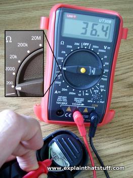
Photo: Measuring resistance with a multimeter.
Using a multimeter like this one, you can automatically find the resistance of an electronic component;
the meter feeds a known current through the component, measures the voltage across it, and uses Ohm's law to calculate the resistance.
Although multimeters are reasonably accurate, you have to remember that the leads and probes also have resistance that will introduce an error into your measurements (the smaller the resistance you're measuring, the bigger the likely error).
Here, I'm measuring the resistance of a loudspeaker in a telephone, which you can see, from the digital display, is 36.4 Ω. Inset: a switch on the multimeter lets me measure a range of different resistances (200 Ω, 2000 Ω, 20K = 20,000 Ω, 200K = 200,000 Ω, and 20M = 20 million Ω).
Sponsored links
Resistance is useless?
How many times have you heard bad guys say that in movies? It's often
true in science as well. If a material has a high resistance, it
means electricity will struggle to get through it. The more the
electricity has to struggle, the more energy
is wasted. That sounds
like a bad idea, but sometimes resistance is far from "useless"
and actually very helpful.
Photo: The filament inside an old-style light bulb. It's a very thin wire with a moderate amount of resistance. It's designed to get hot so it glows brightly and gives off light.
In an old-style light bulb, for example,
electricity is made to flow through an extremely thin piece of wire
called a filament. The wire is so thin that the electricity
really has to fight to get through it. That makes the wire extremely
hot—so much so, in fact, that it gives off light. Without
resistance, light bulbs like this wouldn't function. Of course the
drawback is that we have to waste a huge amount of energy heating up
the filament. Old-style light bulbs like this make light by making
heat and that's why they're called incandescent lamps; newer energy-efficient light bulbs make light without making much heat through the entirely different process of fluorescence.
The heat that filaments make isn't always wasted energy. In appliances like electric kettles, electric radiators,
electric showers, coffee makers, and toasters, there are bigger and more durable versions of filaments called
heating elements. When an electric current flows through them, they get
hot enough to boil your water or cook your bread. In heating elements, at least, resistance is far from useless.
Resistance is also useful in things like transistor radios and TV
sets. Suppose you want to lower the volume on your TV. You turn
the volume knob and the sound gets quieter—but how does that happen?
The volume knob is actually part of an electronic component called a
variable resistor. If you turn the volume down, you're actually
turning up the resistance in an electrical circuit that drives
the TV's loudspeaker. When you turn up the
resistance, the electric
current flowing through the circuit is reduced. With less current,
there's less energy to power the loudspeaker—so it sounds much
quieter.
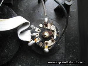
Photo: "Variable resistor" is the very general name for a component whose resistance can be varied by
moving a dial, lever, or control of some sort. More specific kinds of variable resistors include potentiometers (small electronic components with three terminals) and rheostats (usually much larger and made from multiple turns of coiled wire with a sliding contact that moves across the coils to "tap off" some fraction of the resistance). Photos: 1) A small variable resistor acting as the volume control in a transistor radio. 2) Two large rheostats from a power plant. You can
see the dial controls that "tap off" more or less resistance. Photo by Jack Boucher from Historic American Engineering Record courtesy of US Library of Congress.
How resistors work
People who make electric or electronic circuits to do particular
jobs often need to introduce precise amounts of resistance. They can
do that by adding tiny components called resistors. A resistor is a
little package of resistance: wire it into a circuit and you reduce
the current by a precise amount. From the outside, all resistors look
more or less the same. As you can see in the top photo on this page, and the one below,
a resistor is a short, worm-like component with colored stripes on
the side. It has two connections, one on either side, so you can hook
it into a circuit.
Photo: A typical resistor.
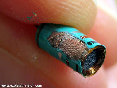
What's going on inside a resistor? If you break one open, and
scratch off the outer coating of insulating paint, you might see
an insulating ceramic rod running through the middle with copper wire wrapped around the outside. A resistor like this is described as wire-wound. The number of copper turns controls the
resistance very precisely: the more copper turns, and the thinner the
copper, the higher the resistance. In smaller-value resistors,
designed for lower-power circuits, the copper winding is replaced by
a spiral pattern of carbon. Resistors like this are much cheaper to
make and are called carbon-film.
Generally, wire-wound resistors are more precise and more stable at higher operating temperatures.
Photo: Inside a wire-wound resistor. Break one in half, scratch away the paint, and you can clearly see the insulating ceramic core and the conducting copper wire wrapped around it.
How does the size of a resistor affect its resistance?
Suppose you're trying to force water through a pipe. Different sorts of pipes will be more or less obliging, so
a fatter pipe will resist the water less than a thinner one and a shorter pipe
will offer less resistance than a longer one. If you fill the pipe with, say, pebbles or sponge, water
will still trickle through it but much more slowly. In other words, the length, cross-sectional area (the area
you see looking into the pipe to see what's inside), and stuff inside the pipe all affect its resistance to water.
Electrical resistors are very similar—affected by the same three factors. If you make a wire thinner or longer, it's harder for electrons to wiggle through it. And, as we've already seen, it's harder for electricity to flow through some materials (insulators) than others (conductors). Although Georg Ohm is best known for relating voltage, current, and resistance, he also researched the relationship
between resistance and the size and type of material from which a resistor is made. That led him to another important equation:
R = ρ × L / A
In simple words, the resistance (R) of a material increases as its length increases (so longer wires offer more resistance) and increases as its area decreases (thinner wires offer more resistance). The resistance is also related to the type of material from which a resistor is made, and that's indicated in this equation by the symbol ρ, which is called the resistivity, and measured in units of Ωm (ohm meters). Different materials have very different resistivities: conductors have much lower resistivity than insulators. At room temperature, aluminum comes in at about 2.8 x 10⁻⁸ Ωm, while copper (a better conductor) is significantly lower at 1.7 −8 Ωm. Silicon (a semiconductor) has a resistivity of about 1000 Ωm and glass (a good insulator)
measures about 1012 Ωm. You can see from these figures how vastly different conductors and insulators are in their ability to carry electricity: silicon is about 100 billion times worse than copper and glass is about a billion times worse again!
Chart: Good conductors: How the resistivity of 10 common metals and alloys compares to that of silver at room temperature. For example, you can see that nichrome, an alloy used in heating elements, has about 66 times more resistance than a similar piece of silver. Data from various sources.
Sponsored links
Resistance and temperature
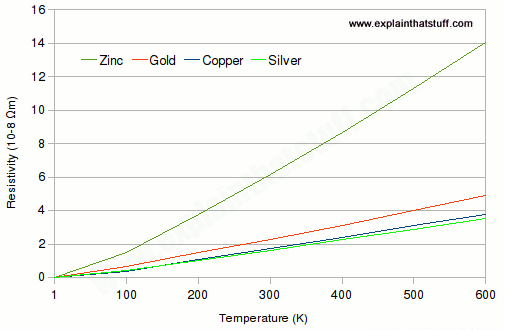
The resistance of a resistor isn't constant, even if it's a certain material of a fixed length and area: it steadily increases as the temperature increases. Why? The hotter a material, the more its atoms or ions jiggle about and the harder it is for
electrons to wriggle through, which translates into higher electrical resistance. Broadly speaking,
the resistivity of most materials increases linearly with temperature (so if you increase the
temperature by 10 degrees, the resistivity increases by a certain amount, and if you increase it
by another 10 degrees, the resistivity rises by the same amount again).
If you cool a material, you lower its resistivity—and if you cool it to an extremely low
temperature, you can sometimes make the resistivity disappear altogether, in a phenomenon known
as superconductivity.
Chart: The resistance of a material increases with temperature. This chart shows how resistivity (basic resistance of a material, independent of its length or area) increases almost linearly as the temperature increases from absolute zero up to about 600K (327°C) for four common metals. Drawn using original data from "Electrical Resistivity of Selected Elements" by P. Desai et al, J. Phys. Chem. Ref. Data, Vol 13, No 4, 1984 and "Electrical Resistivity of Copper, Gold, Palladium, and Silver" by R. Matula, J. Phys. Chem. Ref. Data, Vol 8, No 4, 1979, courtesy of US National Institute of Standards and Technology Open Data.
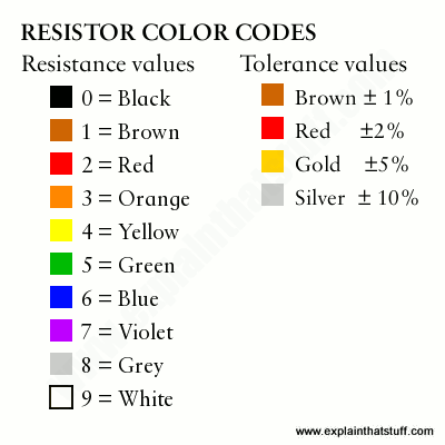
Resistor color codes
You can figure out the resistance of a resistor from the pattern
of colored bands.
On most resistors, you'll see there are three rainbow-colored bands, then a
space, then a fourth band colored brown, red, gold, or silver.
Turn the resistor so the three rainbow bands are on the left.
The first two of the rainbow bands tell you the first two
digits of the resistance. Suppose you have a resistor like the one
shown here, with colored bands that are brown, black, and red and a fourth golden band.
You can see from the color chart below that brown means 1 and black means 0, so the
resistance is going to start with "10". The third band is a decimal multiplier: it tells you
how many powers of ten to multiply the first two numbers by (or how many zeros to add
on the end, if you prefer to think of it that way). Red means 2, so we
multiply the 10 we've got already by 10 × 10 = 100 and get 1000. Our resistor is 1000 ohms.
The final band is called the tolerance and it tells you how
accurate the resistance value you've just figured out is likely to be.
If you have a final band colored gold, it means the resistance is accurate to within
plus or minus 5 percent. So while the officially stated resistance
is 1000 ohms, in practice, the real resistance is likely to be
anywhere between 950 and 1050 ohms.
If there are five bands instead of four, the first three bands give
the value of the resistance, the fourth band is the decimal multiplier,
and the final band is the tolerance. Five-band resistors quoted with three digits and a multiplier,
like this, are necessarily more accurate than four-band resistors, so they have a lower tolerance value.
Sponsored links
Don't want to read our articles? Try listening instead
MAKE Presents: The Resistor: A 5-minute introductory video from Colin Cunningham of MAKE magazine. Covers the basic concept of resistors and a little history, then shows how to make your own resistor with a 2B pencil!
What is a resistor?: This video spends quite a bit of time explaining how to read color codes; if you find the whole color system confusing, this is a good place to get your ideas clear.
Books
For younger readers
Easy Electronics by Charles Platt. Maker Media, 2017. A simplified, comic-style, 50-page introduction with an emphasis on learning by doing.
For older readers
Make: Electronics by Charles Platt. Maker Media, 2015. A longer and more elaborate introduction from Charles Platt, but using the same hands-on approach.
Component of the Month: Resistors by John Baichtal. MAKE, April 1, 2013. An alternative introduction that covers similar ground to this article.
The Mysterious Memristor by Sally Adee. IEEE Spectrum, May 1, 2008. The story of the fourth major circuit element, the memristor (memory resistor).
Please do NOT copy our articles onto blogs and other websites
Articles from this website are registered at the US Copyright Office. Copying or otherwise using registered works without permission, removing this or other copyright notices, and/or infringing related rights could make you liable to severe civil or criminal penalties.