
Thyristors
by Chris Woodford. Last updated: March 30, 2023.
Transistors are the tiny electronic components that changed the world: you'll find them in everything from calculators and computers to telephones, radios, and hearing aids. They're amazingly versatile, but that doesn't mean they can do everything. Although we can use them to switch tiny electrical currents on and off (that's the basic principle behind computer memory), and transform small currents into somewhat larger ones (that's how an amplifier works), they're not very useful when it comes to handling much bigger currents. Another drawback is that they turn off altogether as soon as the switching current is removed, which means they're not so useful in devices such as alarms where you want a circuit to trigger and stay on indefinitely. For those sorts of jobs, we can turn to a somewhat similar electronic component called a thyristor, which has things in common with diodes, resistors, and transistors. Thryristors are reasonably easy to understand, though most of the explanations you'll find online are unnecessarily complex and often confusing beyond belief. So that's our starting point: let's see if we can take a clear and simple look at what thyristors are, how they work, and what kinds of things we can use them for!
Artwork: A typical thyristor looks a bit like a transistor—and works in a closely related way.
Sponsored links

Contents
What are thyristors?
First, let's nail some terminology. Some people use the term silicon-controlled rectifier (SCR) interchangeably with "thyristor." In fact, silicon-controlled rectifier is a brand name that General Electric introduced to describe one particular kind of thyristor that it made. There are various other kinds of thyristors too (including ones called diacs and triacs, which are designed to work with alternating current), so the terms aren't completely synonymous. Nevertheless, this article is about keeping things simple, so we'll just talk about thyristors in the most general terms and assume SCRs are exactly the same thing. We'll refer to them as thyristors throughout.

Photo: Thyristors are widely used in electronic power control circuits like this one.
Three connections
So what is a thyristor? It's an electronic component with three leads called the anode (positive terminal), cathode (negative terminal), and gate. These are somewhat analogous to the three leads on a transistor, which you'll remember are called the emitter, collector, and base (for a conventional transistor) or the source, drain, and gate (in a field-effect transistor, or FET). In a conventional transistor, one of the three leads (the base) acts as a control that regulates how much current flows between the other two leads. The same is true of a thyristor: the gate controls the current that flows between the anode and the cathode. (It's worth noting that you can get thryistors with two or four leads, as well as three-lead ones. But we're keeping things simple here, so we'll just talk about the most common variety.)
Transistors versus thyristors
If a transistor and a thyristor do the same job, what's the difference between them? With a transistor, when a small current flows into the base, it makes a larger current flow between the emitter and the collector. In other words, it acts as both a switch and an amplifier at the same time:

How a transistor works: A small current flowing into the base makes a larger current flow between the emitter and the collector. This is an n-p-n transistor with red indicating n-type silicon, blue indicating p-type, black dots representing electrons and white dots representing holes.
A similar thing happens inside a FET, except that we apply a small voltage to the gate to produce an electric field that helps a current flow from the source to the drain. If we remove the small current at the base (or gate), the large current immediately stops flowing from the emitter to the collector (or from the source to the drain in a FET).
Now often that's not what we want to happen. In something like an intruder alarm circuit (where maybe an intruder steps on a pressure pad and the bells start ringing), we want the small current (activated by the pressure pad) to trip the larger current (the ringing bells) and for the larger current to keep on flowing even when the smaller current stops (so the bells still ring even if our hapless intruder realizes his mistake and steps back off the pad). In a thyristor, that's exactly what happens. A small current at the gate triggers a much larger current between the anode and the cathode. But even if we then remove the gate current, the larger current keeps on flowing from the anode to the cathode. In other words, the thyristor stays ("latches") on and remains in that state until the circuit is reset.
Where a transistor generally deals with tiny electronic currents (milliamps), a thyristor can handle real (electric) power currents (several hundred volts and 5–10 amps is typical). That's why we can use them in such things as factory power switches, speed controls for electric motors, household dimmer switches, car ignition switches, surge protectors, and thermostats. Switching time is practically instantaneous (measured in microseconds), and that useful feature, coupled with a lack of moving parts and high reliability, is why thyristors are often used as electronic (solid-state) versions of relays (electromagnetic switches).
How does a thyristor work?
Thyristors are a logical extension of diodes and transistors, so let's briefly recap on those components. If you're unfamiliar with solid-state electronics, we have longer and clearer explanations of how diodes work and and how transistors work, which you might like to read first.
A thyristor is like two diodes
Recall that a diode is two layers of semiconductor (p-type and n-type) sandwiched together to produce a junction where interesting things happen. According to how you wire up a diode, current will either flow through it or not, making it the electronic equivalent of a one-way street. With a positive connection to the p-type (blue) and a negative connection to the n-type (red), a diode is forward biased, so electrons (black dots) and holes (white dots) move happily across the junction and a normal current flows:
A forward-biased diode: current flows across the junction between the p-type (blue) and n-type (red), carried by electrons (black dots) and holes (white dots).
In the opposite configuration, with a positive connection to the n-type and a negative to the p-type, a diode is reverse biased: the junction becomes a huge chasm that electrons and holes can't cross and no current flows:
A reverse-biased diode: with the battery connected the other way, the "depletion zone" at the junction gets wider, so no current flows.
In a transistor, we have three layers of semiconductor arranged alternately (either p-n-p or n-p-n), giving two junctions where interesting things can happen. (A FET is slightly different, with extra layers of metal and oxide, but still essentially an n-p-n or p-n-p sandwich.). A thyristor is simply the next step in the sequence: four layers of semiconductor, again arranged alternately to give us p-n-p-n (or n-p-n-p if you swap it around) with three junctions in between them. The anode connects to the outer p layer, the cathode to the outer n layer, and the gate to the internal p layer, like this:

A thyristor is like two junction diodes connected together, but with an extra connection to one of the inner layers—the "gate."
You can see that this resembles two junction diodes connected in series, but with the extra gate connection at the bottom. Just like a diode, a thyristor is a rectifier: it conducts in only one direction. You can't make a thyristor simply by wiring two diodes in series: the extra gate connection means there's more to it than that. If you're quite familiar with electronics, you'll note the resemblance between a thyristor and a Shockley diode (a kind of double diode with four alternating semiconductor layers, invented by Transistor pioneer William Shockley in 1956). Thyristors evolved from Shockley's transistor and diode work, which was further developed by Jewell James Ebers, who developed the two-transistor model we're going to cover next.

Artwork: General Electric introduced the first commercially successful thyristor (then called a silicon-controlled rectifier) in July 1957, thanks to the efforts of Robert Hall, Nick Holonyak, F. W. "Bill" Gutzwiller, and others. This is a basic illustration of a thyristor from one of Bill Gutzwiller's patents. Artwork from US Patent 3,040,270: Silicon controlled rectifier circuit including a variable frequency oscillator courtesy of US Patent and Trademark Office.
A thyristor is like two transistors
What's less obvious is that the four layers work like two transistors (an n-p-n and a p-n-p) that are connected together so the output from one forms the input to the other. The gate serves as a kind of "starter motor" to activate them.
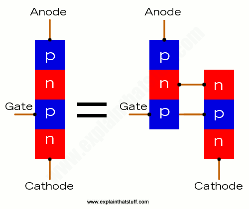
A thyristor is also like two transistors connected together, so the output from each one serves as the input to the other one.
Sponsored links
The three states of a thyristor
So how does this thing work? We can put it into three possible states, in all three of which it's either completely off or completely on, which means it's essentially a binary, digital device. To understand how these states work, it helps to keep diodes and transistors in mind:
Forward blocking
Normally, with no current flowing into the gate, a thyristor is switched off: no current can flow from the anode to the cathode. Why? Think of the thyristor as two diodes joined together. The upper diode and the lower diode are both forward biased. However, that means the junction in the center is reverse biased, so there's no way for current to get all the way from the top to the bottom. This state is called forward blocking. Although it's similar to forward-bias in a conventional diode, no current flows.
Reverse blocking
Suppose we reverse the anode/cathode connections. Now you can probably see that both the upper and lower diodes are reverse biased, so still no current flows through the thyristor. This is called reverse blocking (and it's analogous to reverse bias in a simple diode).
Forward conducting
The third state is the really interesting one. We need the anode to be positive and the cathode negative. Then, when a current flows into the gate, it switches on the lower transistor, which switches on the upper one, which switches on the lower one, and so on. Each transistor activates the other. We can think of this as a kind of internal, positive feedback in which the two transistors keep feeding current to each other until both of them are fully activated, at which point current can flow through them both from the anode to the cathode. This state is called forward conducting and it's how a thyristor "latches" (stays permanently) on. Once a thyristor is latched on like this, you can't turn it off simply by removing the current to the gate: at this point, the gate current is irrelevant—and you have to interrupt the main current flowing through from the anode to the cathode, often by switching off power to the entire circuit. Don't follow that? Check out the animation in the box below, which I hope will make it clear.

