Need to hunt down a problem lurking in an
electric circuit?
You'll need a meter of some kind, maybe even an oscilloscope. Most people use digital meters
these days that show readings of current, voltage, and resistance on an LCD display
(they're sometimes called solid-state or electronic meters). But many of us
still prefer the old kind of meter with a pointer that sweeps back
and forth on a dial. Moving-coil meters, as these things are known, are still
widely used in all kinds of different equipment, from airplane
cockpit instruments to sound-level (VU) meters in recording studios. Let's take
a closer look at how they work!
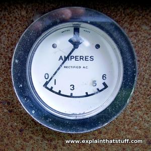
Photo: A typical high-current ammeter on a car battery charger. This one can indicate the approximate size of a current up to 6 amps (A), though the scale isn't marked precisely enough for accurate measurements.
Moving-coil meters work in a similar way to electric motors.
If you know how one of those works, understanding a meter is easy. Either way, let's start from the
beginning.
If you send an electric current down a metal wire, you create a
magnetic field around the wire at the same time. You can't
see it but it's there nevertheless—and you can make it do some very
interesting things. Put a compass near a wire, switch on the current,
and you'll see the needle turn as you do so. Switch off the current
and the needle will flick back again. Roughly speaking, this is the science at work in a moving coil meter: the
electric current passing down a wire creates a magnetic field that
makes a needle flick to one side. But how does that happen, exactly?
Animation: Put a length of wire over a compass and connect it to a battery. When you switch
on the current, it creates a magnetic field all around the wire that makes the compass needle move. Reverse the current
and the compass needle moves in the opposite direction. Use a bigger current and the compass needle moves further.
This experiment shows that electric currents generate magnetic fields and it was first carried out by Danish physicist
Hans Øersted in 1820. It's the basic science behind moving-coil meters.
Inside a meter, a tight coil of copper wire, wrapped
round an iron core, is mounted in between the poles of a permanent
magnet. The coil has connections at either end so you can pass an
electric current through it and it has a long pointer stuck to it
that runs out across the meter dial. When you connect the meter into
a circuit and turn on the current, the current creates a magnetic
field in the coil. The field repels the magnetic field created by the
permanent magnet, making the coil rotate and turning the pointer up
the dial. The more current that flows through the coil, the bigger
the magnetic field it creates, the greater the repulsion, the more the
coil turns, and the further up the dial the pointer goes. So the
pointer gives you a measurement of how much current is passing through the coil.
With appropriate calibration, you can use the dial to measure the current directly.
Meters like this were developed in 1882 by French physicist-physician Jacques-Arsène d'Arsonval.
A few years later, American electrochemist Edward Weston further improved and commercialized the design
(you can see an example of one of his meters further down this page).
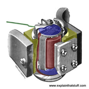
Artwork: Jacques-Arsène d'Arsonval was a pioneer of the practical
moving-coil meter, which used a needle (green) mounted on a coil (red) between magnetic poles (yellow),
and springs (blue) to bring it back to zero when the current stopped flowing.
Artwork from a historic illustration in Dynamometers and the Measurement of Power by John Joseph Flather, John Wiley, 1900.
(I've added the colors for clarity).
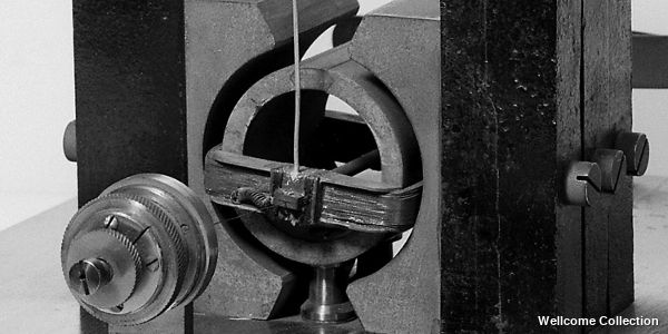
Artwork: A close-up of the coil and magnets in a real d'Arsonval type meter. The needle is the white line pointing straight upward. Photo courtesy of Wellcome Collection published under a Creative Commons (CC BY 4.0) licence.
How moving-coil meters work
With the probes unconnected, the meter is like a circuit broken by an open switch: no current can flow into the meter or the coil inside it.
With no current flowing, the coil generates no magnetic field and the pointer stays at zero.
Connect the meter probes to something you're testing (such as a circuit board), and current will immediately start to flow through the meter and the coil inside it.
The moving current creates a temporary magnetic field around the coil that repels the magnetic field created by the permanent magnet. The strength of the magnetic field is directly related to the size of the current that flows through the coil.
The greater the current, the greater the magnetic field produced by the coil, and the higher up the dial the pointer moves.
It's worth noting briefly that the pointer acts like a lever, magnifying the movement at the
coil and producing a bigger deflection on the dial. In other words, if the coil moves by only a tiny amount, the pointer will move up the dial by a much greater amount that's easier to measure. That helps us make a more accurate measurement.
Sponsored links
Different types of meters
You can use moving-coil meters to measure voltage, current, or resistance—but
you have to connect them up in different ways in each case.
Voltmeters
To measure voltage, you connect a meter in parallel across the
two points of the circuit you want to measure. Voltage-measuring meters are called, not surprisingly,
voltmeters.
Ammeters
To measure current, you place your meter in series (insert it directly into the path of the
circuit). Current-measuring meters are generally called ammeters
(since they measure in amps)
or galvanometers (after Luigi Galvani,
the Italian who famously discovered electric current by making frogs' legs twitch). If large currents are being measured,
ammeters typically need an extra resistance called a shunt
fitted in parallel with their terminals. Most of the current flows
through the shunt, leaving only a small fraction flowing through the
meter coil itself (thus protecting the mechanism). Some ammeters have
dials on their box so you can measure a wide range of different
currents. Turning the dial effectively switches a different-sized
resistance into the measuring circuit, with smaller shunts
(ones with lower resistance) used to measure larger currents.
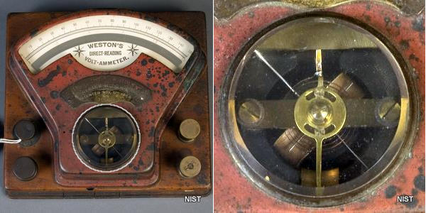
Photo: Moving-coil meters that can measure both volts and amps haven't changed very much. This one is a Direct-Reading Volt-Ammeter developed by Edward Weston of Newark, New Jersey and dating from the late 19th century. Left: You can see the separate brass connections for measuring volts and amps at the bottom and there are two scales at the top, an upper scale that measures 0–150 volts and a lower one measuring 0–1.5 amps. Right: A closeup of the moving magnetic coil. Photo courtesy of
National Institute of Standards and Technology Digital Collections, Gaithersburg, MD 20899.
How does a shunt work?
There's a maximum amount of current you can put through a moving coil meter; if you want to measure currents
bigger than this, you need to use a shunt—a resistor that "shunts" most of the current around a parallel circuit.
It's easy to calculate how big a shunt you need using Ohm's law (V = I×R).
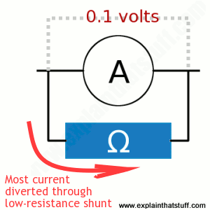
Suppose you have an ammeter (shown here as the circle with an A in it) that has an internal resistance of 10 Ω (ohms) and its needle shows a maximum reading (a so-called "full scale deflection," or FSD) when a current of 10 milliamps (mA), or 10/1000 A, flows through it. With the needle giving a full-scale deflection, Ohm's law tells us the voltage across the meter must be V = (10/1000) × 10 = 0.1 volts (shown by the gray dotted line).
Artwork: An ammeter (A) is a sensitive instrument that measures only relatively small currents. If you want to measure bigger currents, you need to divert a high proportion of them around a "shunt" resistor (Ω). Since the meter and the shunt are in parallel, they have the same voltage across them. We can use this to calculate the size of the shunt resistor we need for measuring any size of current.
The shunt resistor (shown in blue and marked Ω) and the meter are in parallel, so the voltage across the shunt must be the same as the voltage across the meter (0.1 volts).
Now suppose you want to measure currents as big as 2 amps (so the meter shows a full-scale deflection at 2A). In this case, 10 milliamps will still be flowing through the meter (it can't take any more) and the vast majority of the current (1990 milliamps or 1.99 amps) will need to divert through the shunt.
Using Ohm's law a second time, we can calculate that the resistance of the shunt must be R = V / I = 0.1 / 1.99 = 0.05Ω.
Notice that the resistance of the shunt is much lower than the resistance of the meter, which is why most of the current diverts through it. The lower the shunt resistance compared to the meter resistance, the more current will go through it. So if you want to measure even bigger currents, you'll need to use even smaller shunt resistances to divert more current away from the sensitive moving coil meter.
Shunt resistors typically measure less than 1Ω, much smaller
than ordinary resistors (which measure from a few ohms up to millions of ohms or megohms). You'll often hear shunt resistors referred to as milliohm resistors and measured that way too. So, for example, a 0.05Ω shunt resistor might be marked as 50 milliohms (50mΩ).
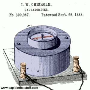
Photo: Galvanometers have quite a lot in common with compasses, which also rely on a magnetic needle moving in a magnetic field. In this early galvanometer design from the 1880s, patented by Isaac Chisholm in 1888, the similarity is obvious: instead of a modern-style pointer and scale, we have a compass needle that swings around when you feed a current into the two wires at the front. Underneath the needle, in the large blue circular box, there's an electromagnet to which the wires are connected. You can find out more about this meter in US Patent 390,067: Galvanometer. Artwork courtesy of US Patent and Trademark Office.
Ohmmeters
You can measure the resistance of a circuit in three ways. You can use an ammeter and
voltmeter to measure the current and voltage and then use Ohm's law. Or you can measure the
resistance in a single operation using a slightly different design
of moving-coil meter called an ohmmeter, which is effectively an
ammeter with its own built-in battery.
The battery provides a voltage of known size. When you place the meter probes across the resistance
you want to measure, you complete a circuit and a current flows. The
meter measures the size of this current, but
shows it as a resistance (the dial is calibrated in ohms based on the
fixed voltage of the battery inside the meter). You can make more
accurate measurements of resistance using a slightly more complex
type of circuit called a Wheatstone bridge.
Moving Coil Meters: more about the theory of meter circuits and the differences between ammeters, voltmeters, and ohmmeters from the excellent Hyperphysics site.
Resistance measurements: A clear explanation of the different ways you can measure resistance, including the Wheatstone bridge.
Books for older readers
Electric Circuits by James William Nilsson and Susan A. Riedel. Pearson, 2015. A long-established, detailed guide to circuits, mostly geared toward electrical engineering and computer science students.
Introduction to Electric Circuits by Richard C. Dorf and James A. Svoboda. Wiley, 2013. Another classic electrical engineering textbook aimed at a similar audience.
Books for younger readers
Easy Electronics by Charles Platt. Maker Media, 2017. This is a simplified version of the author's popular Make Electronics books.
Eyewitness: Electricity by Steve Parker. DK, 2013. There's a strong emphasis on history in this book from the classic DK Eyewitness series.
Please do NOT copy our articles onto blogs and other websites
Articles from this website are registered at the US Copyright Office. Copying or otherwise using registered works without permission, removing this or other copyright notices, and/or infringing related rights could make you liable to severe civil or criminal penalties.